An image intensifier tube is a vacuum tube device for increasing the intensity of available light in an optical system to allow use under low light conditions such as at night, to facilitate visual imaging of low-light processes such as fluorescence of materials to X-rays or gamma rays, or for conversion of non-visible light sources such as near-infrared or short wave infrared to visible. They are used in devices such as night vision goggles.
Introduction[]
Image intensifier tubes (IITs) are an electro-optical device that allows many devices such as night vision devices and medical imaging devices to function. They convert low levels of light from various wavelengths into visible quantities of light at a single wavelength.
History[]
Development of image intensifier tubes began during the 20th century and has led to continuous development since inception.
Pioneering work[]
The idea of an image tube was first proposed by G. Holst and H. De Boer (Netherlands) in 1928 [1] but early attempts to create one were not successful. It was not until 1934 that Holst, working for Philips, created the first successful infrared converter tube. This tube consisted of a photocathode in close proximity to a fluorescent screen. Using a simple lens, an image was focused on the photocathode and a potential difference of several thousand volts was maintained across the tube, causing electrons dislodged from the photocathode by photons to strike the fluorescent screen. This caused the screen to light up with the image of the object focused onto the screen, however the image was non-inverting. With this image converter type tube, it was possible to view infrared light in real time, for the first time.
Generation 0 – early infrared electro-optical image converters[]
Development continued in the US as well during the 1930s and mid-1930, the first inverting image intensifier was developed at RCA. This tube used an electrostatic inverter to focus an image from a spherical cathode onto a spherical screen. (The choice of spheres was to reduce off-axial aberrations.) Subsequent development of this technology led directly to the first Generation 0 image intensifiers which were used by the military during World War II to allow vision at night with infrared lighting for both shooting and personal night vision. The first military night vision device were introduced by the German army as early as 1939, developed since 1935. Early night vision devices based on these technologies were used by both sides in World War II. However, the downside of active night vision (when infrared light is used) is that it is quite obvious to anyone else using the technology.
Unlike later technologies, early Generation 0 night vision devices were unable to significantly amplify the available ambient light and so, to be useful, required the infra-red source. These devices used an S1 photocathode or "silver-oxygen-caesium" photocathode, discovered in 1930 which had a sensitivity of around 60 µA/lm (Microampere per Lumen) and a quantum efficiency of around 1% in the ultraviolet region and around 0.5% in the infrared region. Of note, the S1 photocathode had sensitivity peaks in both the infrared and ultraviolet spectrum and with sensitivity over 950 nm was the only photocathode material that could be used to view infrared light above 950 nm.
Solar blind converters[]
Solar blind photocathodes were not of direct military use and are not covered by "generations". Discovered in 1953 by Taft and Apker [2], they were originally made from cesium telluride. The characteristics of "solar blind" type photocathodes are a response below 280 nm in the ultraviolet spectrum, which is below the wavelength of light that the atmosphere passes through from the sun.
Generation 1 – significant amplification[]
With the discovery of more effective photocathode materials, which increased in both sensitivity and quantum efficiency, it became possible to achieve significant levels of gain over Generation 0 devices. In 1936, the S-11 cathode (cesium-antimony) was discovered by Gorlich, which provided sensitivity of approximately 80 µA/lm with a quantum efficiency of around 20%; this only included sensitivity in the visible region with a threshold wavelength of approximately 650 nm.
It was not until the development of the bialkali antimonide photocathodes (potassium-cesium-antimony and sodium-potassium-antimony) discovered by A.H. Sommer and his later multialkali photocathode (sodium-potassium-antimony-cesium) S20 photocathode discovered in 1956 by accident, that the tubes had both suitable infra-red sensitivity and visible spectrum amplification to be useful militarily. The S20 photocathode has a sensitivity or around 150 to 200 µA/lm. The additional sensitivity made these tubes usable with limited light such as moonlight, while still being suitable for use with low-level infrared illumination.
Cascade (passive) image intensifier tubes[]
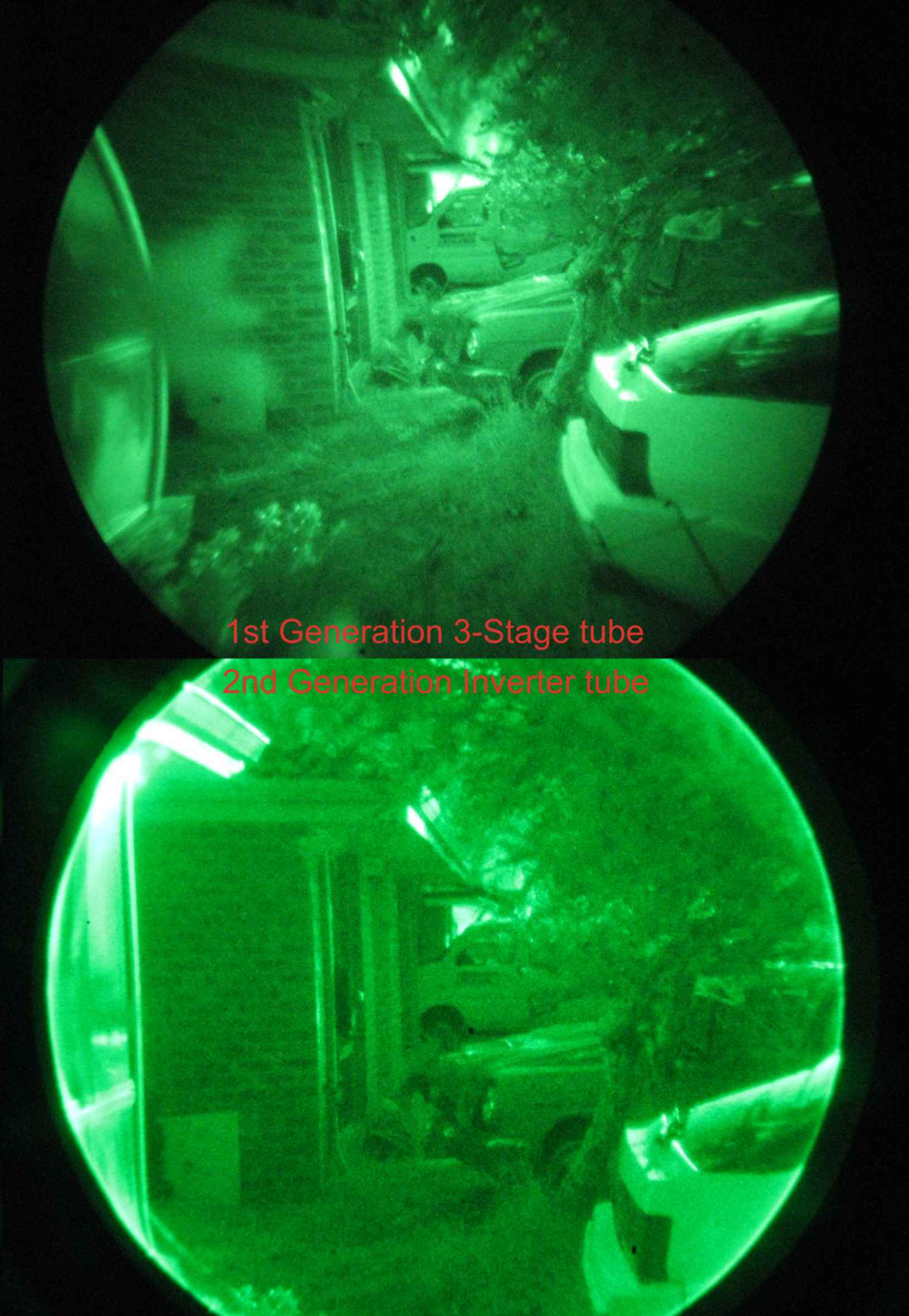
A photographic comparison between a first generation cascade tube and a second generation wafer tube, both using electrostatic inversion, a 25mm photocathode of the same material and the same F2.2 55mm lens. The first generation cascade tube exhibits pincushion distortion while the second generation tube is distortion corrected. All inverter type tubes, including third generation versions, suffer some distortion.
Although originally experimented with by the Germans in World War Two, it was not until the 1950s the U.S. began conducting early experiments using multiple tubes in a "cascade", by coupling the output of an inverting tube to the input of another tube, which allowed for increased amplification of the object light being viewed. These experiments worked far better than expected and night vision devices based on these tubes were able to pick up faint starlight and produce a usable image. However, the size of these tubes, at 17 in (43 cm) long and 3.5 in (8.9 cm) in diameter, were too large to be suitable for military use. Known as "cascade" tubes, they provided the capability to produce the first truly passive night vision scopes. With the advent of fiber optic bundles in the 1960s, it was possible to connect smaller tubes together which allowed for the first true Starlight 'scopes to be developed in 1964. Many of these tubes were used in the AN/PVS-2 rifle 'scope which saw use in Vietnam.
An alternative to the cascade tube explored in the mid 20th century involves optical feedback, with the output of the tube fed back into the input. This scheme has not been used in rifle scopes, but it has been used successfully in lab applications where larger image intensifier assemblies are acceptable.[1]
Generation 2 – the micro-channel plate[]
Second generation image intensifiers use the same multialkali photocathode that the first generation tubes used, however by using thicker layers of the same materials, the S25 photocathode was developed, which provides extended red response and reduced blue response, making it more suitable for military applications. It has a typical sensitivity of around 230 µA/lm and a higher quantum efficiency than S20 photocathode material. Oxidation of the cesium to cesium oxide in later versions improved the sensitivity in a similar way to third generation photocathodes. The same technology that produced the fiber optic bundles that allowed the creation of cascade tubes, with a slight change in manufacturing, allowed the production of micro-channel plates, or MCPs. The micro-channel plate is a thin glass wafer with a Nichrome electrode on either side across which a large potential difference of up to 1000 volts is applied.
The wafer itself is manufactured from many thousands of individual hollow glass fibers, aligned at a "bias" angle to the axis of the tube. The micro-channel plate fits between the photocathode and screen and electrons that strike the side of the "micro-channel" as they pass through it elicit secondary electrons, which in turn elicit additional electrons as they too strike the walls, amplifying the signal. By using the MCP with a proximity focused tube, amplifications of up to 30,000 times with a single MCP layer were possible.By increasing the number of layers of MCP, additional amplification to well over 1,000,000 times could be achieved.
Inversion of Generation 2 devices was achieved through one of two different ways. The Inverter tube uses electrostatic inversion, in the same manner as the first generation tubes did, with a MCP included. Proximity focused second generation tubes could also be inverted by using a fiber bundle with a 180 degree twist in it.
Generation 3 – high sensitivity and improved frequency response[]

A third generation Image Intensifier tube with overlaid detail
The third generation of tubes were fundamentally the same as the second generation, however they possessed two significant differences. Firstly, they used a GaAs/CsO/AlGaAs photocathode which is more sensitive in the 800 nm-900 nm range than second generation photocathodes. Secondly, the photocathode exhibits negative electron affinity (NEA) which provides photoelectrons that are excited to the conduction band a free ride to the vacuum band as the Cesium Oxide layer at the edge of the photocathode causes sufficient band-bending. This makes the photocathode very efficient at creating photoelectrons from photons. The achilles heel of third generation photocathodes however was that they are seriously degraded by positive ion poisoning. Due to the high electrostatic field stresses in the tube and the operation of the MicroChannel Plate, this led to failure of the photocathode within a short period - as little as 100 hours before photocathode sensitivity dropped below Gen2 levels. To protect the photocathode from positive ions and gases produced by the MCP, they introduced a thin film of sintered aluminium oxide attached to the MCP. The high sensitivity of this photocathode, greater than 900 µA/lm, allows more effective low light response, though this was offset by the thin film, which typically blocked up to 50% of electrons. It did allow a significant improvement over second generation systems of the era however even when this was taken into account and the extended sensitivity in the near-infrared region more than made up for the difference as they were more sensitive to the wavelengths of light available from starlight only.
Super second generation[]
Although not formally recognized under the U.S. generation categories, Super Second Generation or SuperGen was developed in 1989 by Jacques Dupuy and Gerald Wolzak. This technology improved the tri-alkali photocathodes to more than double their sensitivity while also improving the microchannel plate by increasing the open-area ratio to 70% while reducing the noise level. This allowed second generation tubes, which are more economical to manufacture, to achieve comparable results to third generation image intensifier tubes. With sensitivities of the photocathodes approaching 700 uA/lm and extended frequency response to 950 nm, this technology continued to be developed outside of the U.S., notably by Photonis and now forms the basis for most non-US manufactured high-end night vision equipment.
Generation 4[]
In 1998, the US company Litton surprised everyone with the development of the filmless image tube. These tubes were original made for the Omni V contract and resulted in significant interest by the US military. However the tubes suffered greatly from fragility during testing and by 2002, the NVESD revoked the fourth generation designation for filmless tubes, at which time they simply became known as Gen III Filmless. These tubes are still produced for specialist uses such as aviation and special operations however are not used for weapon-mounted purposes. To overcome the ion-poisoning problems, they improved scrubbing techniques during manufacture of the MCP ( the primary source of positive ions in a wafer tube ) and implemented autogating, discovering that a sufficient period of autogating would cause positive ions to be ejected from the photocathode before they could cause photocathode poisoning.
Generation III Filmless technology is still in production and use today, but officially, there is no Generation 4 of image intensifiers.
Generation 3 Thin Film[]
Also known as Generation 3 Omni VII and Generation 3+, following the issues experienced with generation IV technology, Thin Film technology became the standard for current image intensifier technology. In Thin Film image intensifiers, the thickness of the film is reduced from around 30 Angstrom (standard) to around 10 Angstrom and the photocathode voltage is lowered. This causes fewer electrons to be stopped than with third generation tubes, while providing the benefits of a filmed tube.
Generation 3 Thin Film technology is presently the standard for most image intensifiers used by the US military.
Terminology[]
There are several common terms used for Image Intensifier tubes.
Gating[]
Gating is a means by which an image intensifier tube may be switched on and off, like an electronic gate. In this respect, the term is the same as used in electronics. Due to the high speed with which image intensifier tubes can be gated, with speeds commonly measured in nanoseconds or even picoseconds, image intensifier tubes are commonly used in research environments where fast events must be photographed. Gated image tubes have been used for such purposes to see the wavefront of burning fuel in an internal combustion engine, allowing better combustion chamber design. Because of the very high speeds with which the shutter may be operated, combined with a light amplification capability, Gated image tubes can even see the travel of light. It is possible to fire a pulsed beam of light at a target and only capture the light reflected from that target by controlling the "gate" shutter to only allow light in that would have returned from the original pulse. Gated-pulsed-active Night Vision devices use this technique, which allows objects to be seen behind obscuring vegetation such as trees or through mist. These devices are particularly useful for seeing objects deep underwater where reflections of light from closer particles would otherwise obscure the image.
Often gating is synchronized to events whose occurrence one cannot control in time. The gating must then be sync'ed to the event itself and be triggered by the event. This is done when the event Triggers the gating electronics. The delay between the event and the start of the gate and the duration of the gate is then controlled by gating electronics e.g. digital delay generators.
Besides operating from an external event, one can use such digital delay generators to initiate an event and then provide the delay and gate timing. They have multiple synchronized outputs which can be used for multiple triggers and gates.
ATG (Auto-gating)[]
Auto-gating is a feature found in many image intensifier tubes manufactured for military purposes after 2006, though it has been around for some time. Autogated tubes gate the image intensifier within so as to control the amount of light that gets through to the microchannel plate. The gating occurs at high frequency and by varying the duty cycle to maintain a constant current draw from the microchannel plate, it is possible to operate the tube during brighter conditions, such as daylight, without damaging the tube or leading to premature failure. Auto-gating of image intensifiers is militarily valuable as it allowed extended operational hours giving enhanced vision during twilight hours while providing better support for soldiers who encounter rapidly changing lighting conditions, such as those assaulting a building.
Sensitivity[]
The sensitivity of an image intensifier tube is measured in Microamperes per Lumen (µA/lm). It defines how many electrons are produced per quantity of light that falls on the photocathode. This measurement should be made at a specific color temperature, such as "at a colour temperature of 2854 K". The color temperature at which this test is made tends to vary slightly between manufacturers. Additional measurements at specific wavelengths are usually also specified, especially for Gen2 devices, such as at 800 nm and 850 nm (infrared). Typically, the higher the value, the more sensitive the tube is to light.
Resolution[]
More accurately known as limiting resolution, tube resolution is measured in line pairs per millimeter or lp/mm. This is a measure of how many lines of varying intensity (light to dark) can be resolved within a millimeter of screen area. However the limiting resolution itself is a measure of the Modulation Transfer Function. For most tubes, the limiting resolution is defined as the point at which the modulation transfer function becomes three percent or less. The higher the value, the higher the resolution of the tube.
An important consideration, however, is that this is based on the physical screen size in millimeters and is not proportional to the screen size. As such, an 18 mm tube with a resolution of around 64 lp/mm has a higher overall resolution than an 8 mm tube with 72 lp/mm resolution. Resolution is usually measured at the centre and at the edge of the screen and tubes often come with figures for both. Military Specification or milspec tubes only come with a criterion such as "> 64 lp/mm" or "Greater than 64 line pairs/millimeter".
Gain[]
The gain of a tube is measured in one of two possible ways. The most common way is cd/m2/lx or candles per meter squared per lux. The other way is to measure gain as Fl/Fc (Foot-lamberts over Foot-candles). This creates issues with comparative gain measurements since neither is a pure ratio, although both are measured as a value of output intensity over input intensity. This creates ambiguity in the marketing of night vision devices as the difference between the two measurements is effectively pi or approximately 3.14159 times. This means that a gain of 10,000 cd/m²/lx is the same as 31.4159 Fl/Fc. With a lack of convention on this item, if the units for gain are not specified, Fl/Fc should typically be assumed.
MTTF (Mean Time To Failure)[]
This value, expressed in hours, gives an idea how long a tube typically should last. It's a reasonably common comparison point, however takes many factors into account. The first is that tubes are constantly degrading. This means that over time, the tube will slowly produce less gain that it did when it was new. When the tube gain reaches 50% of its "new" gain level, the tube is considered to have failed, so primarily this reflects this point in a tube's life.
Additional considerations for the tube lifespan are the environment that the tube is being used in and the general level of illumination present in that environment, including bright moonlight and exposure to both artificial lighting and use during dusk/dawn periods, as exposure to brighter light reduces a tube's life significantly.
Also, a MTTF only includes operational hours. It is considered that turning a tube on or off does not contribute to reducing overall lifespan, so many civilians tend to turn their Night Vision equipment on only when they need to, to make the most of the tube's life. Military users tend to keep equipment on for longer periods of time, typically, the entire time while it is being used with batteries being the primary concern, not tube life.
Typical examples of tube life are:
First Generation: 1000 hrs
Second Generation: 2000 to 2500 hrs
Third Generation: 10000 to 15000 hrs.
Many recent high-end second-generation tubes now have MTTFs approaching 15,000 operational hours.
MTF (Modulation Transfer Function)[]
The Modulation Transfer Function on an image intensifier is a measure of the output amplitude of dark and light lines on the display for a given level of input from lines presented to the photocathode at different resolutions. It is usually given as a percentage at a given frequency (spacing) of light and dark lines. For example, if you look at white and black lines with a MTF of 99% @ 2 lp/mm then the output of the dark and light lines is going to be 99% as dark or light as looking at a black image or a white image. This value decreases for a given increase in resolution also. On the same tube if the MTF at 16 and 32 lp/mm was 50% and 3% then at 16 lp/mm the signal would be only half as bright/dark as the lines were for 2 lp/mm and at 32 lp/mm the image of the lines would be only three percent as bright/dark as the lines were at 2 lp/mm.
Additionally, since the limiting resolution is usually defined as the point at which the MTF is three percent or less, this would also be the maximum resolution of the tube. The MTF is affected by every part of an image intensifier tube's operation and on a complete system is also affected by the quality of the optics involved. Factors that affect the MTF include transition through any fiber plate or glass, at the screen and the photocathode and also through the tube and the microchannel plate itself. The higher the MTF at a given resolution, the better.
See also[]
- Night vision device
- X-ray image intensifier
- Intensified CCD camera
References[]
- ↑ Martin L. Perl and Lawrence W. Jones, Optical Feedback Image Intensifying System, U.S. Patent 3,154,687, Oct. 27, 1964.
- Historical information on IIT development and inception [3]
- Discovery of other photocathode materials [4]
- Several references are made to historical data noted in "Image Tubes" by Illes P Csorba ISBN 0-672-22023-7
- Selected Papers on Image tubes ISBN 0-8194-0476-4
- Make Time for the Stars by Antony Cooke
The original article can be found at Image intensifier and the edit history here.