| Fw 190 | |
|---|---|
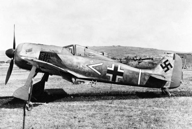 | |
| Fw 190A-3 of Stab. 7./JG2, June 1942.[N 1] | |
| Role | Fighter |
| Manufacturer | Primarily Focke-Wulf Flugzeugbau AG, but also AGO, Arado, Fieseler, Mimetall, Norddeutsche Dornier and others |
| Designer | Kurt Tank |
| First flight | 1 June 1939 |
| Introduction | August 1941 |
| Retired | 1945 (Luftwaffe); 1949 (Turkey) |
| Primary users | Luftwaffe Hungarian Air Force Turkish Air Force |
| Produced | 1941–45; 1996: 16 reproductions |
| Number built | Over 20,000 |
| Variants | Ta 152 |
The Focke-Wulf Fw 190 Würger (English: Shrike) was a German single-seat, single-engine fighter aircraft designed by Kurt Tank in the late 1930s and widely used during World War II. Powered by a radial engine, the 190 had ample power and was able to lift larger loads than its well-known counterpart, the Messerschmitt Bf 109. The 190 was used by the Luftwaffe in a wide variety of roles, including day fighter, fighter-bomber, ground-attack aircraft and, to a lesser degree, night fighter.
When the Fw 190 started flying operationally over France in August 1941, it quickly proved itself to be superior in all but turn radius to the Royal Air Force's main front-line fighter, the Spitfire Mk. V,[2] especially at low and medium altitudes. The 190 maintained superiority over Allied fighters until the introduction of the improved Spitfire Mk. IX in July 1942 restored qualitative parity.[3] The Fw 190 made its air combat debut on the Eastern Front in November/December 1942; though Soviet pilots considered the Bf 109 the greater threat, the Fw 190 made a significant impact. The fighter and its pilots proved just as capable as the Bf 109 in aerial combat, and in the opinion of German pilots who flew both, provided increased firepower and manoeuvrability at low to medium altitude.
The Fw 190 became the backbone of the Jagdwaffe (Fighter Force), along with the Bf 109. On the Eastern Front, the Fw 190 was versatile enough to use in Schlachtgeschwader (Battle Wings or Strike Wings), specialised ground attack units which achieved much success against Soviet ground forces. As an interceptor, the Fw 190 underwent improvements to make it effective at high altitude, enabling it to maintain relative parity with its Allied opponents. The Fw 190A series' performance decreased at high altitudes (usually 6,000 m (20,000 ft) and above), which reduced its effectiveness as a high-altitude interceptor, but this problem was mostly rectified in later models, particularly in the Junkers Jumo 213 inline-engine Focke-Wulf Fw 190D series, which was introduced in September 1944. In spite of its successes, it never entirely replaced the Bf 109.
The Fw 190 was well liked by its pilots. Some of the Luftwaffe's most successful fighter aces claimed a great many of their kills while flying it, including Otto Kittel, Walter Nowotny and Erich Rudorffer.
Early development[]
Genesis[]
In autumn 1937, the German Ministry of Aviation asked various designers for a new fighter to fight alongside the Messerschmitt Bf 109, Germany's front line fighter. Although the Bf 109 was an extremely competitive fighter, the Ministry of Aviation was worried that future foreign designs might outclass it, and wanted to have new aircraft under development to meet these possible challenges.[4]
Kurt Tank responded with a number of designs, most incorporating liquid-cooled inline engines. However, it was not until a design was presented using the air-cooled, 14-cylinder BMW 139 radial engine that the Ministry of Aviation's interest was aroused. As this design used a radial engine, it would not compete with the inline-powered Bf 109 for engines, when there were already too few DB 601's to go around.[5] This was not the case for competing advanced designs like the Heinkel He 100 or Focke-Wulf Fw 187, where production would compete with the 109 or Messerschmitt Bf 110 for engine supplies. After the war, Tank denied a rumour that he had to "fight a battle" with the Ministry to convince them of the radial engine's merits.[6]
Design concepts[]
At the time, the use of radial engines in land-based fighters was relatively rare in Europe, as it was believed that their large frontal area would cause too much drag on something as small as a fighter. Tank was not convinced of this, having witnessed the successful use of radial engines by the US Navy, and felt a properly streamlined installation would eliminate this problem.[5]
The hottest point on any air-cooled engine are the cylinder heads, located along the outside diameter of a radial engine. In order to provide sufficient air to cool the engine, airflow had to be maximized at this outer edge, which was normally accomplished by leaving the majority of the front face of the engine open to the air. During the late 1920s, NACA led development of a dramatic improvement by placing an airfoil-shaped ring around the outside of the cylinder heads (the NACA cowling). The shaping accelerated the air as it entered the front of the cowl, increasing the total airflow, and allowing the opening in front of the engine to be made smaller.[7]
Tank introduced a further refinement to this basic concept. He suggested placing most of the airflow components on the propeller itself, in the form of a oversized propeller spinner whose outside diameter was the same as the engine itself. The cowl around the engine proper was greatly simplified, essentially a basic cylinder. Air entered through a small hole at the center of the propeller, and was directed through ductwork in the spinner so it was blowing rearward along the cylinder heads. To provide enough airflow, a cone was placed in the center of the hole, over the propeller hub, which was intended to compress the airflow and allow a smaller opening to be used. In theory, the tight-fitting cowling also provided some thrust due to the compression and heating of air as it flowed through the cowling.[8]
As to the rest of the design philosophy, Tank wanted something more than an aircraft built only for speed. Tank outlined the reasoning:
The Messerschmitt 109 [sic] and the British Spitfire, the two fastest fighters in world at the time we began work on the Fw 190, could both be summed up as a very large engine on the front of the smallest possible airframe; in each case armament had been added almost as an afterthought. These designs, both of which admittedly proved successful, could be likened to racehorses: given the right amount of pampering and easy course, they could outrun anything. But the moment the going became tough they were liable to falter. During World War I, I served in the cavalry and in the infantry. I had seen the harsh conditions under which military equipment had to work in wartime. I felt sure that a quite different breed of fighter would also have a place in any future conflict: one that could operate from ill-prepared front-line airfields; one that could be flown and maintained by men who had received only short training; and one that could absorb a reasonable amount of battle damage and still get back. This was the background thinking behind the Focke-Wulf 190; it was not to be a racehorse but a Dienstpferd, a cavalry horse.[9]
One of the main features of the Fw 190 was its wide-tracked, inwards-retracting landing gear. Tank appreciated that operating from primitive airfields in wartime would require a stable undercarriage — a lesson learned from witnessing the difficulty of moving machinery in the First World War. The wide-track landing gear spacing gave it better ground handling characteristics, and it suffered fewer ground accidents than the Bf 109 with its narrow-track landing gear. The undercarriage was designed to withstand a sink rate of 15 feet per second (4.5 meters per second, 900 feet per minute), double the strength factor usually required. Hydraulic wheel brakes were used.[10]
Most aircraft of the era used cables and pulleys to operate their controls. The cables tended to stretch, resulting in the sensations of "give" and "play" that made the controls less crisp and responsive, and required constant maintenance to correct. For the new design, the team replaced the cables with rigid pushrods and bearings to eliminate this problem.[N 2] Another innovation was making the controls as light as possible. The maximum resistance of the ailerons was limited to eight pounds, as the average man's wrist could not exert a greater force. The empennage (tail assembly) featured relatively small and well-balanced horizontal and vertical surfaces.[11]
The design team also attempted to minimize changes in the aircraft's trim at varying speeds, thus reducing the pilot's workload. They were so successful in this regard that they found in-flight-adjustable aileron and rudder trim tabs were not necessary. Small, fixed tabs were fitted to control surfaces and adjusted for proper balance during initial test flights. Only the elevator trim needed to be adjusted in flight (a feature common to all aircraft). This was accomplished by tilting the entire horizontal tailplane with an electric motor, with an angle of incidence ranging from -3° to +5°.[12]
Another aspect of the new design was the extensive use of electrically powered equipment instead of the hydraulic systems used by most aircraft manufacturers of the time. On the first two prototypes, the main landing gear was hydraulic. Starting with the third prototype, the undercarriage was operated by push buttons controlling electric motors in the wings, and was kept in position by electric up and down-locks.[13] The armament was also loaded and fired electrically. Tank believed that service use would prove that electrically powered systems were more reliable and more rugged than hydraulics, electric lines being much less prone to damage from enemy fire.[11]
As was the case for the 109, the 190 featured a fairly small wing planform with relatively high wing loading. This presents a trade-off in performance; an aircraft with a smaller wing suffers less drag in most flight and therefore flies faster and may have better range. However, it also means the wing cannot generate extra lift as easily, which is needed for maneuvering or flight at high altitudes.The wings spanned 9.5 m (31 ft 2 in) and had an area of 15 m² (161 ft²). The wing was designed using the NACA 23015.3 airfoil at the root and the NACA 23009 airfoil at the tip.[14]
Earlier designs generally featured canopies consisting of small plates of perspex in a metal framework, and the fuselage running horizontally back from the top of the canopy frame. This design considerably limited visibility, especially to the rear. The introduction of vacuum forming led to the creation of the "bubble canopy" which was largely self-supporting, and could be mounted above the fuselage, offering greatly improved all-round views. Tank's new design included such a design that used only a single frame where the front and rear sections met, just in front of the pilot.
First prototypes[]
Fw 190 V1 in its original form with the streamlined engine cowling and ducted spinner. The pointed tip of the internal spinner can also be seen. Pilot is probably Hans Sander.
The first prototype, the Fw 190 V1 (civil registration D-OPZE), powered by a 1,550 PS (1,529 hp, 1,140 kW) BMW 139 14-cylinder two-row radial engine, first flew on 1 June 1939. It soon showed exceptional qualities for such a comparatively small aircraft, with excellent handling, good visibility and speed (initially around 610 km/h (380 mph)).[15] The roll rate was 162° per second at 410 km/h (255 mph), but the aircraft had a high stall speed of 205 km/h (127 mph).
The cockpit, located directly behind the engine, quickly became uncomfortably hot. During the first flight, the temperature reached 55 °C (131 °F), after which Focke Wulf's chief test pilot, Hans Sander commented, "It was like sitting with both feet in the fireplace."[16] Flight tests soon showed that the expected benefits of Tank's cooling design did not materialize, so after the first few flights, this arrangement was replaced by a smaller, more conventional spinner that covered only the hub of the three-blade VDM propeller.
In an attempt to increase airflow over the tightly cowled engine, a 10-blade fan was fitted at the front opening of the redesigned cowling and was geared to be driven at 3.12 times faster than the propeller shaft's speed. This quickly became standard on the Fw 190 and nearly all other German aircraft powered by the BMW 801.[17] In this form the V1 first flew on 1 December 1939, having been repainted with the Luftwaffe's Balkenkreuz and with the Stammkennzeichen (factory code) RM+CA.[18]
The Fw 190 V2, designated with the Stammkennzeichen alphabetic ID code of FL+OZ (later RM+CB) first flew on 31 October 1939 and was equipped from the outset with the new spinner and cooling fan. It was armed with one Rheinmetall-Borsig 7.92 mm (.312 in) MG 17 machine gun and one 13 mm (.51 in) synchronized MG 131 machine gun in each wing root.[18]
Later prototypes, BMW 801[]
Fw 190 V5k. This is the V5 with the original small wing. The 12-blade cooling fan and redesigned undercarriage and canopy fairings are visible.
Even before the first flight of the Fw 190 V1, BMW was bench testing a larger, more powerful 14-cylinder two-row radial engine, the BMW 801. This engine introduced a pioneering example of an engine management system called the Kommandogerät (command-device): in effect, an electro-mechanical computer which set mixture, propeller pitch (for the constant speed propeller), boost, and magneto timing. This reduced the pilot's work load to moving the throttle control only, with the rest of the associated inputs handled by the Kommandogerät. The drawback was slight and minor surges that made the Fw 190 harder to fly in close formations.[19] Tank asserted the device did not work well.
Another problem was the violent switching in of the high gear of the supercharger as the aircraft climbed. During a test flight, Tank carried out a loop at medium altitude. Just as he was nearing the top of the loop, at 2,650 m (8,700 ft), the supercharger's high gear kicked in with a jerk. The Fw 190 was on its back, with little airspeed. The sudden change in torque hurled the aircraft into a spin. Tank's artificial horizon toppled (the cause is not explained). Although Tank did not know whether he was in an upright or inverted spin, he managed to recover after a loss of altitude. The rough transition was smoothed out and the supercharger's gear-change could engage without incident.[20]
The RLM convinced Focke-Wulf and BMW to abandon the 139 engine in favour of the new engine. The BMW 801 engine was similar in diameter to the 139, although it was heavier and longer by a considerable margin. This required Tank to redesign the Fw 190, and resulted in the abandonment of the V3 and V4. The V5 became the first prototype with the new engine, being fitted with the 1,560 PS (1,539 hp, 1,147 kW) BMW 801 C-0. Much of the airframe was strengthened and in order to balance the heavier engine, the cockpit was moved back in the fuselage and the engine mounted on longer struts. This had the side-effect of reducing the troubles with high temperatures and for the first time provided space for nose armament. It also reduced visibility in nose-high attitudes, notably when taxiing on the ground.
A 12-blade cooling fan replaced the earlier 10-blade unit, and was likewise installed in front of the engine's reduction gear housing, still running with the original 3.12:1 reduction ratio, which was standardised for BMW-powered Fw 190s. The propeller shaft passed through the fan's central plate, which was made of cast magnesium. The fan provided cooling air not only for the engine cylinders' fins, but also for the BMW-designed annular oil cooler, which was located in the forward part of the cowling. The oil cooler was protected by an armoured ring which made up the front face of the cowling.[18] A small hole in the centre of the spinner also directed airflow to ancillary components.[21] Even with the new engine and the cooling fan, the 801 suffered from high rear-row cylinder head temperatures, which in at least one case resulted in the detonation of the fuselage-mounted MG 17 ammunition.
The vertical tail shape was also changed and the rudder tab was replaced by a metal trim strip adjustable only on the ground. New, stiffer undercarriage struts were introduced, along with larger diameter wheels. The retraction mechanism was changed from hydraulic to electrically powered, which became a hallmark of later Focke-Wulf aircraft system designs, and new fairings of a simplified design were fitted to the legs.[18] Another minor change was that the rearmost sections of the sliding canopy were redesigned by replacing the plexiglas glazing with duralumin panels. As this section was behind the pilot's seat, there was little visibility lost.
At first, the V5 used the same wings as the first two prototypes, but to allow for the larger tyres, the wheelwells were enlarged by moving forward part of the leading edge of the wing root; the wing area became 15.0 m² (161 ft²). The V5 first flew in the early spring of 1940. The weight increase with all of the modifications was substantial, about 635 kg (1,400 lb), leading to higher wing loading and a deterioration in handling. Plans were made to create a new wing with more area to address these issues. In its original form, this prototype was called the V5k for kleine Fläche (small surface).[22]
In August 1940 a collision with a ground vehicle damaged the V5 and it was sent back to the factory for major repairs. This was an opportune time to rebuild it with a new wing which was less tapered in plan than the original design, extending the leading and trailing edges outward to increase the area. The new wing had an area of 18.30 m² (197 ft²), and now spanned 10.506 m (34 ft 5 in). After conversion, the aircraft was called the V5g for große Fläche (large surface). Although it was 10 km/h (6 mph) slower than when fitted with the small wing, V5g was much more manoeuvrable and had a faster climb rate.[22] This new wing platform was to be used for all major production versions of the Fw 190.[18]
Pre-production, Fw 190 A-0[]

Side-view of Fw 190 A-0
Fw 190 A-0 were the pre-production series ordered in November 1940, with a total of 28 were built. Because they were built before the new wing design was fully tested and approved, the first nine A-0s had small wings. All were armed with a total of six .30 calibre-class machine guns — two synchronised 7.92 mm (.312 in) MG 17 machine guns mounted in the forward fuselage, one similarly synchronized MG 17 in each wing root, and one MG 17 in each of the outboard wings. They were different from later A-series Fw 190s: they had shorter spinners, the armoured cowling ring was a different shape, with a scalloped hinge on the upper, forward edge of the upper engine cowling, and the bulges covering the interior air intakes on the engine cowlings were symmetrical "teardrops". Also, the panels aft of the exhaust pipes had no cooling slots. Several of these aircraft were later modified for testing engines and special equipment.[18]
The first unit to be equipped with the A-0 was Erprobungsstaffel 190, formed in March 1941 to help iron out any technical problems and approve the new fighter before it would be accepted for full operational service in mainstream Luftwaffe Jagdgeschwader. At first, this unit, commanded by Oblt. Otto Behrens, was based at the Luftwaffe's central Erprobungsstelle facility at Rechlin, but it was soon moved to Le Bourget. Engine problems plagued the 190 for much of its early development, and the entire project was threatened several times with a complete shutdown. Had it not been for the input of Behrens and Karl Borris, both of whom had originally enlisted in the Luftwaffe as mechanics, the Fw 190 program might have died before reaching the front lines. Both men indicated that the Fw 190's outstanding qualities outweighed its deficiencies during several Ministry of Aviation commissions that wished to terminate the program.[23] Some 50 modifications were required before the Ministry of Aviation approved the Fw 190 for deployment to Luftwaffe units.[23]
Fw 190 A[]
A-1[]


Fw 190 A-0s or A-1s of an unknown unit.
The Fw 190 A-1 rolled off the assembly lines in June 1941. The first few models were shipped to the Erprobungsstaffel (formerly from II./JG 26 Schlageter) for further testing. Following this testing, the Fw 190 A-1 entered service with II./JG 26, stationed near Paris, France. The A-1 was equipped with the BMW 801 C-1 engine, rated at 1,560 PS (1,539 hp, 1,147 kW) for take-off. Armament consisted of two fuselage-mounted 7.92 mm (.312 in) MG 17s, two wing root-mounted 7.92 mm (.312 in) MG 17s - with all four MG 17s synchronized to fire through the propeller arc - and two outboard wing-mounted 20 mm MG FF/Ms.[24] The new longer propeller spinner and the cowling bulges, which became asymmetrical "teardrops" in shape, remained the same for the rest of the A-series. The panel immediately behind the exhaust outlets was unslotted, although some A-1s were retrofitted with cooling slots. A new hood jettisoning system, operated by an MG FF cartridge, was introduced. The pilot's head armour changed in shape and was supported by two thin metal struts in a "V" shape attached to the canopy sides.[24] The standard radio fitted was the FuG 7, although some A-1s were also equipped with FuG 25 "Erstling" IFF (identification friend or foe) equipment.[24] The A-1 models still suffered from the overheating that prototype Fw 190s had experienced during testing. After only 30–40 hours of use (sometimes less), many of these early engines had to be replaced.[25] Focke-Wulf completed 102 A-1s at the Bremen and Marienburg factories between June and October 1941. Also in October, a further order of 315 A-1s, subcontracted to AGO Flugzeugwerke at its Oschersleben factory, began to be built as A-2s.[24]
A-2[]


Side-view of Fw 190 A-2; the most notable change over the A-0 was the addition of three vertical cooling slits on the engine cowling, just forward of the wing.
The introduction of the BMW 801 C-2 resulted in the Fw 190 A-2 model, first introduced in October 1941. As part of this upgrade, a modification to the exhaust system devised by III./JG 26's Technical Officer ("T.O.") Rolf Schrödeter was added. There were 13 exhausts for the 14 cylinders; eight of these were grouped to exit, four on each side, along the forward fuselage, just above the leading edge of the wing; under the forward centre section, between the undercarriage bays were five exhaust stacks, with cylinders 9 and 10 sharing a common pipe.[26] To quickly implement the fix, it was found that the re-routing could be done easily in Gruppe workshops. The reduction in temperature affecting the bottom cylinder went a long way to solving the problem.[27][28] The addition of new ventilation slots on the side of the fuselage further aided cooling, and with the widespread availability of the A-2 in the spring of 1942, the overheating problems were greatly reduced.
The A-2 wing weaponry was updated, with the two wing root-mounted 7.92 mm (.312 in) MG 17s being replaced by 20 mm MG 151/20E cannon.[29] With the introduction of the new cannon, the Revi C12/C gunsight was upgraded to the new C12/D model. The introduction of the A-2 marked a shift in air supremacy from the British, with their Spitfire Mk V, to the Germans.[29][N 3] German production records make no real distinction between A-2s and A-3s, which were very similar aircraft: the total combined production was 910 airframes between October 1941 and August 1942.[30] In addition to Focke-Wulf and AGO, a new subcontractor, Arado, built A-2s and A-3s at Warnemünde.[29]
A-3[]


Fw 190A-3 of JG 1 in the Netherlands, summer 1942.
The Fw 190 A-3 was equipped with the BMW 801 D-2 engine, which increased power to 1,700 PS (1,677 hp, 1,250 kW) at takeoff by improving the supercharger and raising the compression ratio. Because of these changes, the A-3 model required a higher octane fuel—100 (C3) versus 87 (B4).[26] The A-3 retained the same weaponry as the A-2.[31] The A-3 also introduced the Umrüst-Bausätze factory conversion sets. The Fw 190 A-3/U1 and U2 were single experimental Fw 190s: U1 (W.Nr 130270) was the first 190 to have the engine mount extended by 15 cm (6 in), which would be standardized on the later production A-5 model. The U2 (W.Nr 130386) had RZ 65 73 mm (2.87 in) rocket launcher racks under the wings with three rockets per wing. There were also a small number of U7 aircraft tested as high-altitude fighters armed with only two 20 mm MG 151 cannon, but with reduced overall weight.[32]
The Fw 190 A-3/U3 was the first of the Jabo (Jagdbomber), using an ETC-501 centre-line bomb rack able to carry up to 500 kg (1,100 lb) of bombs or, with horizontal stabilising bars, one 300 L (80 US gal) drop tank. The U3 retained the fuselage-mounted 7.92 mm (.312 in) MG 17s and the wing-mounted 20 mm MG 151 cannon, with the outer MG FF being removed.[32] [N 4]
The Fw 190 A-3/U4 was a reconnaissance version with two RB 12.5 cameras in the rear fuselage and a EK 16 gun camera or a Robot II miniature camera in the leading edge of the port wing root. Armament was similar to the U3, however, and the ETC 501 was usually fitted with a 300 L (80 US gal) drop tank.[32] See A-2 for production numbers.[33]
In autumn 1942, a political decision diverted 72 new aircraft to Turkey in an effort to keep that country friendly to the Axis powers. These were designated Fw 190 A-3a (a=ausländisch (foreign), designation for export models) and delivered between October 1942 and March 1943. The Turkish aircraft had the same armament as the A-1: four 7.92 mm (.312 in) synchronized MG 17 machine guns and two 20 mm MG FF cannon. There was no FuG 25 IFF device in the radio equipment.[32]
A-4[]


A captured Fw 190A-4. Because the aircraft had been repainted while being tested by the USAAF, the Balkenkreuz and swastika are incorrect in size and proportions.
Introduced in July 1942, the Fw 190 A-4 was equipped with the same engine and basic armament as the A-3. Updated radio gear, the FuG 16Z, was installed replacing the earlier FuG VIIa. A new, short "stub" vertical aerial mount was fitted to the top of the tailfin, a configuration which was kept through the rest of the production Fw 190s. In some instances, pilot-controllable engine cooling vents were fitted to the fuselage sides in place of the plain slots. Some A-4s were outfitted with a special Rüstsatz field conversion kit, comprising the fitting of a pair of under-wing Werfer-Granate 21 (BR 21) rocket mortars, and were designated Fw 190 A-4/R6. However, the A-4's main improvement was the number of Umrüst-Bausätze factory-refit package enhanced versions.
The U1 was outfitted with an ETC 501 rack under the fuselage. All armament except for the MG 151 cannon was removed. The U3 was very similar to the U1, and later served as the Fw 190 F-1 assault fighter. Some U3s used for night operations had a landing light mounted in the leading edge of the left wing-root. The U4 was a reconnaissance fighter, with two Rb 12.4 cameras in the rear fuselage and an EK 16 or Robot II gun camera. The U4 was equipped with fuselage-mounted 7.92 mm (.312 in) MG 17s and 20 mm MG 151 cannon. The U7 was a high-altitude fighter, easily identified by the compressor air intakes on either side of the cowling. Adolf Galland flew a U7 in the spring of 1943.
The A-4/U8 was the Jabo-Rei (Jagdbomber Reichweite, long-range fighter-bomber), adding a 300 L (80 US gal) drop tank under each wing, on VTr-Ju 87 racks with duralumin fairings produced by Weserflug, and a centreline bomb rack. The outer wing-mounted 20 mm MG FF/M cannon and the cowling-mounted 7.92 mm (.312 in) MG 17 were removed to save weight. The A-4/U8 served as the model for the Fw 190 G-1.
A new series of easier-to-install Rüstsatz field kits began to be produced in 1943. The first of these, the A-4/R1, was fitted with a FuG 16ZY radio set with a Morane "whip" aerial fitted under the port wing. These aircraft, called Leitjäger or Fighter Formation Leaders, could be tracked and directed from the ground via special R/T equipment called Y-Verfahren. More frequent use of this equipment was made from the A-5 onwards.[34] The Fw 190A-4 could achieve 1,700 hp (2,100 with MW-50 boost). Its maximum speed was 416 mph (670 km/h) at 20,590 ft (6,250 m). Operational ceiling was 37,400 ft (11,400 m). Normal range was 497 miles (800 km). Normal takeoff weight was 8,378 lb (3,800 kg).[35] A total of 976 A-4s were built between June 1942 and March 1943.[36]
A-5[]


Fw 190A-5 with the under-wing WGr 21 rocket-propelled mortar. The weapon was developed from the 21 cm Nebelwerfer 42 infantry weapon.
The Fw 190 A-5 was developed after it was determined that the Fw 190 could easily carry more ordnance. The D-2 engine was moved forward another 15 cm (6 in) as had been tried out earlier on the service test A-3/U1 aircraft, moving the center of gravity forward to allow more weight to be carried aft. Some A-5s were tested with the MW 50 installation: this was a mix of 50% methyl alcohol and 50% water, which could be injected into the engine to produce a short-term power boost to 2,000 PS (1,973 hp, 1,471 kW), but this system was not adopted for serial production. New radio gear, including FuG 25a Erstling IFF, and an electric artificial horizon found their way into the A-5.[34] The A-5 retained the same basic armament as the A-4.
The A-5 too, saw several Umrüst-Bausätze kits. The U2 was designed as a night Jabo-Rei and featured anti-reflective fittings and exhaust flame dampeners. A centre-line ETC 501 rack typically held a 250 kg (550 lb) bomb, and wing-mounted racks mounted 300 L drop tanks. A EK16 gun camera, as well as landing lights, were fitted to the wing leading edge. The U2 was armed with only two 20 mm MG 151 cannon. The U3 was a Jabo fighter fitted with ETC 501s for drop tanks and bombs; it too featured only two MG 151s for armament. The U4 was a "recon" fighter with two RB 12.5 cameras and all armament of the basic A-5 with the exception of the MG FF cannon. The A-5/U8 was another Jabo-Rei outfitted with SC-250 centreline-mounted bombs, under-wing 300-litre drop tanks and only two MG 151s; it later became the Fw 190 G-2. A special U12 was created for bomber attack, outfitted with the standard 7.92 mm (.312 in) MG 17 and 20 mm MG 151 but replacing the outer wing 20 mm MG-FF cannon with two underwing gun pods containing two 20 mm MG 151/20 each, for a total of two machine guns and six cannon. The A-5/U12 was the prototype installation of what was known as the R1 package from the A-6 onwards. The A-5/R11 was a night fighter conversion fitted with FuG 217 Neptun (Neptune) radar equipment with arrays of three dipole antenna elements vertically mounted fore and aft of the cockpit and above and below the wings. Flame-dampening boxes were fitted over the exhaust exits. 1,752 A-5s were built from November 1942 to June 1943.[37]
A-6[]
The Fw 190 A-6 was developed to address shortcomings found in previous "A" models when attacking U.S. heavy bombers. Modifications of the type to date had caused the weight of the aircraft to creep up. To combat this and to allow better weapons to be installed in the wings, a structurally redesigned and lighter wing was introduced. The normal armament was increased to two MG 17 fuselage machine guns and four 20 mm MG 151/20E wing root and outer wing cannon with larger ammunition boxes. New electrical sockets and reinforced weapon mounts were fitted internally in the wings to allow the installation of either 20 mm or 30 mm (1.18 in) ammunition boxes and for underwing armament. Because the outer wing MG 151s were mounted lower than the MG/FFs new larger hatches, incorporating bulges and cartridge discharge chutes, were incorporated into the wing lower surfaces. It is believed the MG 17s were kept because their tracer rounds served as a targeting aid for the pilots. A new FuG 16 ZE radio navigation system was fitted in conjunction with a FuG 10 ZY. A loop aerial for radio navigation, mounted on a small "teardrop" base was fitted under the rear fuselage, offset slightly to port, with an additional short "whip" aerial aft of this. These aerials were fitted on all later Fw 190 variants.
The A-6 was outfitted in numerous ways with various sets, Rüstsätze (field modification kits); more flexible than the factory upgrade kits for previous versions, these field upgrade kits allowed the A-6 to be refitted in the field as missions demanded. At least 963 A-6s were built from July 1943 ending in April 1944, according to Ministry of Aviation acceptance reports and Focke-Wulf production books. In late 1943, the Erla Antwerp factory designed a simpler rack/drop-tank fitting, which was more streamlined than the bulky ETC 501 and could be quickly fitted or removed. Several A-6s, A-7s and A-8s of JG 26 were fitted with these racks (one such aircraft was A-8 W.Nr.170346 Black 13 flown by Obstlt. Josef Priller during the Normandy invasion on 6 June 1944.)
A-7[]
The Fw 190 A-7 was based on the Fw 190 A-5/U9 prototype, and entered production in November 1943. The A-7 was equipped with the BMW 801 D-2 engine, again producing 1,700 PS (1,677 hp, 1,250 kW). Designed to combat the USAAF's heavy bombers the basic armament was upgraded to include two fuselage-mounted 13 mm (.51 in) MG 131s, replacing the MG 17s. Because the larger-breeched MG 131s had to be mounted further apart, the upper gun cowling, just in front of the cockpit, was modified with faired bulges and a new upper engine cowling was manufactured. This left insufficient room for the three cowling toggle latches, which were moved to the side panels. The rest of the armament fit stayed the same as earlier versions; two wing root-mounted 20 mm MG 151s and two outer wing-mounted 20 mm MG 151s. The Revi gunsight was updated to the new 16B model. The additional weight of the new weapon systems required strengthening of the wheels, adding a reinforced rim to better deal with typical combat airfield conditions. The A-7 was usually outfitted with the centreline-mounted ETC 501 rack. There were several major Rüstsätze for the A-7, many including Werfer-Granate 21 WGr 21 rockets. A total of 701 A-7s were produced from November 1943 to April 1944, according to Ministry of Aviation acceptance reports and Focke-Wulf production books.[38]
A-8[]

An Fw 190 A-8/R2 in American hands. "White 11" of 5./JG 4 was captured during Operation Bodenplatte after its engine had been damaged by American light flak.
The Fw 190 A-8 entered production in February 1944, powered either by the standard BMW 801 D-2 or the 801Q (also known as 801TU). The 801Q/TU, with the "T" signifying a Triebwerksanlage unitized powerplant installation, was a standard 801D with improved, thicker armour on the front annular cowling, which also incorporated the oil tank, upgraded from 6 mm (.24 in) on earlier models to 10 mm (.39 in). Changes introduced in the Fw 190 A-8 also included the C3-injection Erhöhte Notleistung emergency boost system to the fighter variant of the Fw 190 A (a similar system with less power had been fitted to some earlier Jabo variants of the 190 A), raising power to 1,980 PS (1,953 hp, 1,456 kW) for a short time. The Erhöhte Notleistung system operated by spraying additional fuel into the fuel/air mix, cooling it and allowing higher boost pressures to be run, but at the cost of much higher fuel consumption. From the A-8 on, Fw 190s could be fitted with a new paddle-bladed wooden propeller, easily identified by its wide blades with curved tips. A new outwardly bulged main canopy glazing format, more in the manner of a Malcolm hood rather than a bubble canopy, with greatly improved vision sideways and forward, had been developed for the F-2 ground attack model, but was often seen fitted at random on A-8s, F-8s and G-8s. The new canopy included a larger piece of head armour which was supported by reinforced bracing and a large fairing. A new internal fuel tank with a capacity of 115 L (30 US gal) was fitted behind the cockpit, which meant that the radio equipment had to be moved forward to just behind the pilot.


Three-side-view of Fw 190 A-8
Externally, a large round hatch was incorporated into the lower fuselage to enable the new tank to be installed, and the pilot's oxygen bottles were moved aft and positioned around this hatch. A fuel filler was added to the port side, below the rear canopy and a rectangular radio access hatch was added to starboard. Other changes included an ETC 501 underfuselage rack which was mounted on a lengthened carrier and moved 200 mm (8 in) further forward to help restore the centre of gravity of the aircraft. This fuselage would form the basis for all later variants of the Fw 190 and the Ta 152 series. The Morane "whip" aerial for the Y-Verfahren was fitted as standard under the port wing, just aft of the wheelwell. Nearly a dozen Rüstsätze kits were made available for the A-8, including the famous A-8/R2 and A-8/R8 Sturmbock models. The A-8/R2 replaced the outer wing 20 mm cannon with a 30 mm (1.18 in) MK 108 cannon. The A-8/R8 was similar, but fitted with heavy armour including 30 mm (1.18 in) canopy and windscreen armour and 5 mm (.2 in) cockpit armour. The A-8 was the most numerous of the Fw 190 As, with over 6,655 A-8 airframes produced from March 1944 to May 1945. A-8s were produced by at least eight factories during its lifetime.[39]
A-9[]
The Fw 190 A-9 was the last A-model produced, and was first built in September 1944. The A-9 was fitted with the new BMW 801S, called the 801 TS or 801 TH when shipped as a more complete Triebwerksanlage version of the modular Kraftei or "power egg" concept, unitized engine installation (an aircraft engine installation format embraced by the Luftwaffe for a number of engine types on operational aircraft, in part for easy field replacement) rated at 2,000 PS (1,973 hp, 1,471 kW); the more powerful 2,400 PS (2,367 hp, 1,765 kW) BMW 801F-1 was still under development, and not yet available. The armour on the front annular cowling, which also incorporated the oil tank, was upgraded from the 6 mm (.24 in) on earlier models to 10 mm (.39 in). The 12-blade cooling fan was initially changed to a 14-blade fan, but it consumed more power to operate and did not really improve cooling; thus BMW reverted to the 12-blade fan. The A-9 cowling was slightly longer than that of the A-8 due to a larger annular radiator within the forward cowl for the oil system. The bubble canopy design with the larger head armour was fitted as standard. Three types of propeller were authorised for use on the A-9: the VDM 9-112176A wooden propeller, 3.5 m (11 ft 6 in) in diameter, was the preferred option, however, many A-9s were fitted with the standard VDM 9-12067A metal propeller and some had a VDM 9-12153A metal propeller with external, bolt on balance weights.[40] The A-9 was also designed originally as an assault aircraft, so the wing leading edges were to have been armoured; however, this did not make it past the design stage in order to save weight. The A-9 was very similar to the A-8 in regards to the armament and Rüstsätze kits. A total of 910 A-9s were built between April 1944 and May 1945, mostly in Focke Wulf's Cottbus factory.[41]
A late-war attempt was made with the Fw 190 A-10, which was to have begun arriving in pilots' hands by March 1945 and was to be fitted with larger wings for better maneuverability at higher altitudes, which, due to internal space, could have allowed additional 30 mm (1.18 in) calibre, long-barreled MK 103 cannon to be fitted. The A-10 was to be powered by the 801 F engine. However, due to the priority given to the Dora variant of the Fw 190 and the new Ta 152, the A-10 never made it past the prototype stage.[42]
Total A-series Production[]
Across all variants, 13,291 Fw 190 A-model aircraft were produced.[43] This total may, however, include rebuilt or modified airframes from earlier airframes. The Luftwaffe frequently changed between models on the production line, and it would not have been uncommon for an A5 variant to be converted into an A7 or A8 aircraft. This was especially true for older, battle-damaged aircraft that were upgraded to whatever current version the factory was manufacturing at the time of repair. The other complicating factor, sometimes making detailed compilation impossible is that many aircraft were assembled in field workshops where airframes and engines from aircraft withdrawn from service units were recycled.[44]
High-altitude developments[]
Limitations of A series[]
The BMW 139 (and the 801 that followed) had originally been designed as a high-power replacement for earlier engines like the BMW 132 that were used primarily on low-altitude cargo aircraft and bombers. As a result, the designers had not invested much effort in producing high performance superchargers for it.
Even before the Fw 190 A was put into service, its high-altitude performance was seen to be deficient. In contrast, the Daimler-Benz DB 601 engines used on the Bf 109 featured an advanced fluid-coupled, single stage, variable speed supercharger that provided excellent boost across a wide range of altitudes. The 190's short wings also presented a problem at higher altitudes, where they were highly loaded. As a result, the 190 could not compete with the 109 at altitudes above 20,000 ft (6,100 m), which is one reason that the 109 remained in production until the end of the war. This was not a serious concern at the time of introduction, as most combat was taking place at medium altitudes, where the 190 had ample performance.
However, as the air war reached higher altitudes with the widespread introduction of turbocharged US bombers, the need for improved performance became pressing. As a result, GM-1 Nitrous oxide boost was introduced to provide more power at altitude, but this was complex and gave boosted performance for only a short period of time.[45]
High altitude improvements[]


The Fw 190C V18 prototype, with large ventral "pouch" fairing for the turbocharger installation and broader-chord vertical fin/rudder.
Tank started looking at ways to address the altitude performance problem early in the program. In 1941, he proposed a number of versions featuring new powerplants, and he suggested using turbochargers in place of superchargers. Three such installations were outlined; the Fw 190 B with a turbocharged BMW 801, the Fw 190 C with a turbocharged Daimler-Benz DB 603, and the Fw 190 D with a supercharged Junkers Jumo 213. The aircraft would also include a pressurized cockpit and other features making them more suitable for high-altitude work. Prototypes for all three models were ordered.[46]
Fw 190 V12 (an A-0) would be outfitted with many of the elements which eventually led to the B series. As it was based on the same BMW 801 engine as the A models, airframe modifications were relatively minor. These included a pressurized cockpit which doubled the panes of glass in the canopy so that hot air could be forced between them to prevent icing, and the addition of the GM-1 nitrous oxide injection system. Several problems were encountered during the machine's flight and ground trials, mostly caused by the pressurisation system for the cockpit, and for this reason the first B-series testbed airframe was retired from active service in late 1942. However, trials on other aircraft continued in early 1943, when the first few Fw 190 A-1s were modified into B-series testbeds. The same aircraft used for testing the pressurized cockpits were also used to test larger wings (20.3 m²/219 ft² versus the standard 18.3 m²/197 ft² wing). This work seriously interfered with the studies on pressurised cockpits. Following these studies, one additional Fw 190 B was built, named the B-1. This aircraft was similar to the B-0, but had slightly different armament. In its initial layout, the B-1 was to be fitted with four 7.92 mm (.312 in) MG 17s and two 20 mm MG-FFs. One was fitted with two MG 17s, two 20 mm MG 151s and two 20 mm MG-FFs. After the completion of W.Nr. 811, no further Fw 190 B models were ordered.
The C model's use of the longer DB 603 engine required more extensive changes to the airframe. As the weight was distributed further forward, the tail of the aircraft had to be lengthened in order to maintain the desired centre of gravity. To test these changes, several examples of otherwise standard 190 As were re-engined with a supercharged DB 603 to experiment with this engine fit, V13 (W.Nr. 0036) with the 1,750 PS 603A, the similar V15 and V16, a 1,800 DB 603 E being fitted to the latter after a time. With this engine, the V16 was able to reach 725 km/h (450 mph) at 6,800 m (22,310 ft), a considerable improvement over the 650 km/h (400 mph) at 5,200 m (17,060 ft) of the basic A models. V18 followed, the first to feature the full high-altitude suite of features, including the pressurized cockpit, longer wings, a 603G engine driving a new four-blade propeller, and a Hirth 9-2281 turbocharger. Unlike the experimental B models, V18 had a cleaner turbocharger installation, running the required piping along the wing root, partially buried in the fillet, and installing both the turbocharger air intake and intercooler in a substantially sized teardrop shaped fairing under the cockpit.[47] This "pouch" led to the "Känguruh" (Kangaroo) nickname for these models. V18 was later modified to the V18/U1, with a "downgraded" 603A engine, but a new DVL turbocharger that improved power to 1,600 PS at an altitude of 10,700 m (35,105 ft). Four additional prototypes based on the V18/U1 followed: V29, V30, V32 and V33.
Like the C models, the early examples of the D models were built primarily to test fit the Jumo 213 engine to the existing airframe, as the D-0, with plans to move on to definitive high-altitude models later, the D-1 and D-2. The first D-0 prototype was completed in October 1942, consisting of an A-5 airframe with the Jumo 213A engine. Further examples followed, but like the C models the development was stretched out.
Fw 190D[]
Fw 190D-9[]
A early production Fw 190 D-9, W.Nr. 210??? at the Cottbus plant. Note the early canopy and redesigned, simplified centreline rack carrying a 300 l drop tank.[48]
The Fw 190 D (nicknamed the Dora; or Long-Nose Dora, "Langnasen-Dora") was intended to improve on the high-altitude performance of the A-series enough to make it useful against the American heavy bombers of the era. In the event, the D series was rarely used against the heavy-bomber raids, as the circumstances of the war in late 1944 meant that fighter-versus-fighter combat and ground attack missions took priority. A total of 1,805 D-9s were produced.[49] Production started in August 1944.[49]
With the D version the power plant was changed from the radial engine of earlier models to a 12-cylinder inverted-Vee liquid-cooled engine. The Jumo 213A generated 1,750 PS (1,726 hp, 1,287 kW), and could produce 2,100 PS (2,071 hp, 1,545 kW) of emergency power with MW 50 injection, improving performance to 426 mph (686 km/h) at 21,650 ft (6,600 m). In order to fit the new engine in the Fw 190 fuselage while maintaining proper balance, both the nose and the tail of the aircraft were lengthened, adding nearly 1.52 m (4.99 ft) to the fuselage, bringing the overall length to 10.192 m (33.438 ft) versus the 9.10 m (29.9 ft) of the late war A-9 series. The lengthened tail required a straight-sided bay, 30 cm (12 in) long, spliced in forward of the rear angled joint and tail assembly of the fuselage. To further aid balance, the pilot's oxygen bottles were moved aft and located in the new bay. This gave the rear fuselage a "stretched" appearance.[50]
Furthermore, the move to a V12 engine from a radial engine required more components to be factored into the design, most significantly the need for coolant radiators (radial engines are air-cooled). To keep the design as simple and as aerodynamic as possible, Tank used an annular radiator (the AJA 180 L) installed at the front of the engine, similar to the configuration used in the Jumo powered versions of the Junkers Ju 88. The annular radiator with its adjustable cooling gills resembled a radial engine installation, although the row of six short exhausts stacks on either side of the elongated engine cowling showed that Jumo 213 was an inverted vee-12 engine.[51] While the first few Doras were fitted with the flat-top canopy, these were later replaced with the newer rounded top "blown" canopy first used on the A-8 model. With the canopy changes, the shoulder and head armour plating design was also changed. Some late model Doras were also fitted with the Ta 152 vertical stabilizer and rudder, often called "Big Tails" by the Luftwaffe ground crews and pilots, as seen on W.Nr. 500647 Brown 4 from 7./JG 26 and W.Nr. 500645 Black 6 from JG 2. The centreline weapons rack was changed to an ETC 504 with a simplified and much smaller mounting and fairing.[50]
Early D-9s reached service without the MW 50 installation, but in the meantime Junkers produced a kit to increase manifold pressure (Ladedrucksteigerungs-Rüstsatz) that increased engine output by 150 PS to 1,900 PS, and was effective up to 5,000 m (16,400 ft) altitude. It was fitted immediately to D-9s delivered to the units from September, or retrofitted in the field by TAM. By the end of December, all operational Doras, 183 in total, were converted.[52] From November 1944, a simplified methanol water (MW 50) system (Oldenburg) was fitted, which boosted output to 2,100 PS. By the end of 1944, 60 were delivered with the simplified MW 50 system or were at the point of entering service. The 115 L tank of the Oldenburg system would hold the MW 50 booster liquid, which was single purpose, while later systems were to be dual purpose, holding either MW 50 or additional fuel.[53]
The fighter lacked the higher rate of roll of its close coupled radial-engined predecessor. It was a bit faster, however, with a maximum speed of 680 km/h (422 mph) at 6,600 meters (21,650 ft). Its 2,240 horsepower with methanol-water injection (MW 50) gave it an excellent acceleration in combat situations. It also climbed and dived more rapidly than the Fw 190A, and so proved well suited to the dive-and-zoom ambush tactics favored by the Schlageter fighter wing's pilots from November 1944 onward, when the wing converted to the Fw 190D. Many of the early models were not equipped with tanks for methanol for the MW 50 boost system, which was in very short supply in any event. At low altitude, the top speed and acceleration of these examples were inferior to those of Allied fighters. Hans Hartigs recalled that only one of the first batch of Dora 9s received by the First Gruppe had methanol water injection, and the rest had a top speed of only 590 km/h (360 mph).[54]
Owing to the failure of multiple attempts to create an effective next-generation 190, as well as the comments of some Luftwaffe pilots, expectations of the Dora project were low. These impressions were not helped by the fact that Tank made it very clear that he intended the D-9 to be a stopgap until the Ta 152 arrived. These negative opinions existed for some time until positive pilot feedback began arriving at Focke-Wulf and the Luftwaffe command structure.[55] Sporting good handling and performance characteristics, the D-9 made an effective medium altitude, high speed interceptor, although its performance still fell away at altitudes above about 20,000 ft (6,100 m). When flown by capable pilots, the Fw 190D proved the equal of Allied types.[56][57]


This captured Fw 190 D-9 appears to be a late production aircraft built by Fieseler at Kassel. It has a late style canopy; the horizontal black stripe with white outline shows that this was a II.Gruppe aircraft.
As it was used in the anti-fighter role, armament in the "D" was generally lighter compared to that of the earlier aircraft—usually the outer wing cannon were dropped so that the armament consisted of two 13 mm (.51 in) MG 131, with 400 rounds per gun, and two 20 mm MG 151/20E cannon with 250 rounds per gun; all four weapons were synchronized to fire through the propeller arc.[58] The wings of the D-9 still had the electrical circuits and attachment points for the underwing WGr 21 rocket propelled mortar, although none appeared to have used these operationally.[59] While inferior to the A-series in roll rate, the "D" was superior in turn rate, climb, dive and horizontal speed. The Dora still featured the same wing as the A-8, however, and was capable of carrying outer wing cannon as well, as demonstrated by the D-11 variant, with a three-stage supercharger and four wing cannon (two MG 151s and two MK 108s).[60] The first Fw 190 D-9s started entering service in September 1944, with III./JG 54. It was quickly followed by other units including I./JG 26 which flew its last operations on the A-8s on 19 November 1944.[61]
Some Fw 190 Ds served as fighter cover for Messerschmitt Me 262 airfields, as the jet fighters were very vulnerable on take-off and landing. These special units were known as Platzsicherungstaffel (airfield defence squadrons).[62] One unit, known as the Würger-Staffel, was created in April 1945 by Leutnant Heinz Sachsenberg at the behest of Adolf Galland, and was part of JV 44. The role of the Staffel was to guard the airfield and JV 44's Me 262s as they landed; as such the Fw 190s were supposed to take off before the jets and circle the airfield in pairs (a Rotte). However, to allow the 262s a clear run back to the airfield the 190s had to land before the jets, negating their protection.[63] To help anti-aircraft artillery protecting the airfields to quickly identify friendly aircraft, the under-surfaces of the Würger-Staffel 190s were painted red with narrow white stripes.[64] leading to the alternative nickname of Papageien Staffel (parrot squadron) from the bright red color. (Britain's Hawker Typhoons had a similar profile to the Fw 190, and were also painted with "invasion stripes" until early 1944, to aid identification in combat.)
Fw 190 D-11[]
17 Fw 190 D-11s were known to have been manufactured. This version was fitted with the uprated Jumo 213F series engine similar to the Jumo 213E used in the Ta-152 H series but minus the intercooler. Visible changes over the D-9 were the enlarged supercharger air intake on the starboard side cowling and the use of a wooden, broad-bladed VS 9 or 10 propeller unit utilizing three 9-27012 C-1 blades with a diameter of 3.6 m (11.8 ft). The 13 mm (.51 in) fuselage guns were removed, and the cowling redesigned by omitting the gun troughs and simplifying to a flat profile. Two 30 mm (1.18 in) MK 108 cannons were installed in the outer wings to complement the 20 mm MG 151s in the inboard positions. Of the 17 Dora-11s delivered, three can be accounted for. One, the best known, was Rote 4 (red 4) of JV 44's Platzschutz unit. Another, white chevron, was found at München-Riem, and may have served with JV 44 after serving at the Verbandsführerschule General der Jagdflieger (Training School for Unit Leaders) at Bad Wörishofen; it is not known if it was actually used operationally. A third, "white <61," was also found after the war at the Verbandsfuehrerschule General der Jagdflieger.[65]
Fw 190 D-12[]
While the D-11 was under manufacture, work started on the Fw 190 D-12 and D-13 models. These were similar to the D-11, but featured Motorkanone nose cannons firing through the propeller hub. The D-12 would mount the 30 mm (1.18 in) MK 108 cannon and the D-13 would be fitted with a 20 mm MG 151/20 cannon. There were three test aircraft built for the D-12 line, V63, V64 and V65, but no production aircraft were built and the D-13 was selected instead.
Fw 190 D-13[]


Fw 190 D-13/R11, Champlin Fighter Museum, Phoenix, Arizona (c.1995)
The Fw 190 D-13 started with the construction of two prototypes (W.Nr 732053 and W.Nr 7322054), and the 20 mm MG 151/20 cannon was found to be quite suited for the aircraft and was already well known to be effective against allied bombers, as well as an effective ground support weapon. Thus the Fw 190 D-13/Rüstsatz 11 (/R11) version was selected to enter production. The D-13/R11 was fitted with all-weather flying equipment including the PKS12 and K-23 systems for steering and autopilot. The FuG 125 radio system, known as Hermine was fitted to the aircraft, as well as a heated windscreen. Pilots reported that due to the large amounts of torque produced by the engine, they usually used the steering system during the takeoff run as it helped with the rudder movements. The D-13 also introduced a hydraulic boost system for the ailerons, which was later used on the Ta 152.
One example of the D-13 version still exists in the 21st century in the markings of "Yellow 10" of 6 Staffel/JG 26, and is being prepared to once again be airworthy[66] in the United States.
D-series production[]
In all, the Ministry of Aviation called for 820 D-11 airframes to be built by Focke-Wulf Sorau, starting in early 1945, Fieseler Kassel was tasked to build 1,420 D-12s starting in the same time frame and the manufacture of the D-13 was passed to Arbeitsgruppe Roland [N 5] tasked with the construction of 1,060 airframes starting again in early 1945. For some yet unknown reason, production of the D-12 was cancelled in favour of the D-13 model. From evidence from the Oberkommando der Luftwaffe General Quartiermeister document Nr. 2766/45 of April 1945, it was known that 17 D-13s were more than likely built, but only two were known to be in service. A D-13 (Wk. Nr 836017) flown by the Geschwaderkommodore of JG 26, Franz Götz, an ace with 63 kills, was surrendered to the British at Flensburg, Northern Germany in May 1945.[68] As noted previously, this aircraft is still in existence, painted in its original colour scheme as Yellow 10 of 6 Staffel/JG 26, is thought to be airworthy and is currently located in the Flying Heritage Collection at Paine Field in Everett, Washington. This aircraft is one of the few existing Fw 190s with a provenance that can be traced continuously from its manufacture to the present time.[69]
Ground attack variants[]
Fw 190 F[]


The National Air & Space Museum's restored Fw 190 F-8 in late war markings
The Fw 190 F was originally manufactured as a Fw 190 A-0/U4. Early testing started in May 1942. The A-0 testbed aircraft was outfitted with centreline and wing-mounted ETC 50 bomb racks. The early testing results were quite good, and Focke-Wulf began engineering the attack version of the Fw 190. New armor was added to the bottom of the fuselage, protecting the fuel tanks and pilot, the engine cowling, and the landing gear mechanisms and outer wing mounted armament. Finally, the Umrüst-Bausatz kit 3 (abbreviated as /U3) was fitted to the aircraft by means of a ETC 501 or ER4 centreline mounted bomb rack and up to a SC250 bomb under each wing. This aircraft was designated the Fw 190 F-1. The first 30 Fw 190 F-1s were renamed Fw 190 A-4/U3s; however, Focke-Wulf quickly began assembling the aircraft on the line as Fw 190 F-1s as their own model, with 18 more F-1s built before switching to the F-2. The Fw 190 F-2s were renamed Fw 190 A-5/U3s, which again were soon assembled as Fw 190 F-2s on the production line. There were 270 Fw 190 F-2s built according to Focke-Wulf production logs and Ministry of Aviation acceptance reports.[citation needed]
The Fw 190 F-3 was based on the Fw 190 A-5/U17, which was outfitted with a centreline mounted ETC 501 bomb rack, and in the Fw 190 F-3/R1 and Fw 190 F-3/R-3, two double ETC 50 bomb racks under each wing or two similarly located 30 mm MK 103 cannons. The F-3 could carry a 66-Imp gal (300 liter) drop tank. A total of 432 Fw 190 F-3s were built.[70]
Owing to difficulties in creating an effective strafing Fw 190 F able to take out the Soviet T-34 tank, the F-4 through F-7 models were abandoned, and all attempts focused on conversion of the Fw 190 A-8.
The Fw 190 F-8 differed from the A-8 model in having a slightly modified injector on the compressor which allowed for increased performance at lower altitudes for several minutes. The F-8 was also fitted with the improved FuG 16 ZS radio unit, which provided much better communication with ground combat units. Armament of the Fw 190 F-8 was two 20 mm MG 151/20 cannon in the wing roots and two 13 mm (.51 in) MG 131 machine guns above the engine. According to Ministry of Aviation acceptance reports, at least 3,400 F-8s were built, and probably several hundred more were built in December 1944 and from February to May 1945. (Data for these months is missing and probably lost.)[citation needed] Dozens of F-8s served as various testbeds for anti-tank armament, including the WGr.28 280 mm air-to-ground missile, probably based on the projectiles from the Nbw 41 heavy ground-barrage rocket system, and the 88 mm (3.46 in) Panzerschreck 2 rockets, Panzerblitz 1 and R4M rockets.
There were also several Umrüst-Bausätze kits developed for the F-8, which included the Fw 190 F-8/U1 long range JaBo, fitted with underwing V.Mtt-Schloß shackles to hold two 300 L (80 US gal) fuel tanks. ETC 503 bomb racks were also fitted, allowing the Fw 190 F-8/U1 to carry one SC 250 bomb under each wing and one SC 250 bomb on the centreline.
The Fw 190 F-8/U2 torpedo bomber was fitted with an ETC 503 bomb rack under each wing and a centre-line mounted ETC 504. The U2 was also equipped with the TSA 2 A weapons sighting system that improved the U2's ability to attack seaborne targets with a 1,543 lb (700 kg) BT 700.[70]
The Fw 190 F-8/U3 heavy torpedo bomber was outfitted with an ETC 502, which allowed it to carry one BT-1400 heavy torpedo (3,086 lb/1400 kg). Owing to the size of the torpedo, the U3's tail gear needed to be lengthened. The U3 also was fitted with the 2,000 PS BMW 801S engine, and the tail from the Ta 152.[citation needed]
The Fw 190 F-8/U4, created as a night fighter, was equipped with flame dampers on the exhaust and various electrical systems such as the FuG 101 radio altimeter, the PKS 12 automatic pilot, and the TSA 2 A sighting system. Weapons fitted ranged from torpedoes to bombs[citation needed]; however, the U4 was fitted with only two MG 151/20 cannon as fixed armament.
The Fw 190 F-9 was based on the Fw 190 A-9, but with the new Ta 152 tail unit, a new bulged canopy as fitted to late-build A-9s, and four ETC 50 or ETC 70 bomb racks under the wings. According to Ministry of Aviation acceptance reports, 147 F-9s were built in January 1945, and perhaps several hundred more from February to May 1945. (Data for these months is missing and probably lost.)[citation needed]
Fw 190 G[]

Fw 190 G-1 showing the ETC 250 bomb rack, carrying a 250 kg (550 lb) bomb, and the underwing drop tanks on VTr-Ju 87 mounts.
The Fw 190 G was built as a long-range attack aircraft (JaBo Rei, or Jagdbomber mit vergrösserter Reichweite). Following the success of the Fw 190 F as a Schlachtflugzeug (close support aircraft), both the Luftwaffe and Focke-Wulf began investigating ways of extending the range of the Fw 190 F. From these needs and tests, the Fw 190 G was born.
There were four distinct versions of the Fw 190 G:
The Fw 190 G-1: The first Fw 190 Gs were based on the Fw 190 A-4/U8 JaBo Rei's. Initial testing found that if all but two wing root mounted 20 mm MG 151 cannons (with reduced ammunition load) were removed, the Fw 190 G-1 (as it was now called) could carry a 250 kg (550 lb) or 500 kg (1,100 lb) bomb on the centreline and, via an ETC 250 rack, up to a 250 kg (550 lb) bomb under each wing. Typically the G-1s flew with underwing fuel tanks, fitted via the VTr-Ju 87 rack. The FuG 25a IFF (identification friend/foe) was fitted on occasion as well as one of the various radio direction finders available at the time. With the removal of the fuselage mounted MG 17s, an additional oil tank was added to support the BMW 801 D-2 engine's longer run times.[citation needed]
The Fw 190 G-2: The G-2 was based on the Fw 190 A-5/U8 aircraft. The G-2s were similarly equipped to the G-1s; however, due to wartime conditions, the underwing drop tank racks were replaced with the much simpler V.Mtt-Schloß fittings, to allow for a number of underwing configurations. Some G-2s were also fitted with the additional oil tank in place of the MG 17s; however, not all were outfitted with the oil tank. Some G-2s were fitted with exhaust dampers and landing lights in the left wing leading edge for night operations.[citation needed]
The Fw 190 G-3: The G-3 was based on Fw 190 A-6. Like the earlier G models, all but the two wing root mounted MG 151 cannons were removed. The new V.Fw. Trg bombracks, however, allowed the G-3 to simultaneously carry fuel tanks and bomb loads. Because of the range added by two additional fuel tanks, the G-3's duration increased to two hours, 30 minutes. Due to this extra flight duration, a PKS 11 autopilot was fitted. Some G-3s built in late 1943 were also fitted with the a modified 801 D-2 engine which allowed for increased low-altitude performance for short periods of time. The G-3 had two primary Rüstsätze kits. The R1 replaced the V.Fw. Trg racks with WB 151/20 cannon pods. This gave the G-3/R1 a total of six 20 mm cannons. When fitted with the R1 kit, the G model's addition armor was typically not used, and the PKS11 removed. The G-3/R1 was used in both ground strafing and anti-bomber roles. The R5 was similar to the R1, but the V.Fw. Trg racks were removed, and two ETC 50 racks per wing were added. As with the R1, the additional armor from the base G model were removed, as was the additional oil tank. In some instances, the fuselage mounted MG 17s were refitted.[citation needed]
The Fw 190 G-8: The G-8 was based on the Fw 190 A-8. The G-8 used the same "bubble" canopy as the F-8, and was fitted with underwing ETC 503 racks that could carry either bombs or drop tanks. Two primary Rüstsätze kits were also seen on the F-8. The R4 kit was a planned refit for the GM 1 engine boost system, but never made it into production, and the R5 kit replaced the ETC 503 racks with two ETC 50 or 71 racks. Due to the similarities with the F-8, the G-8 was only in production for a short amount of time.[citation needed] Some Gs were field modified to carry 1,000 kg (2,210 lb), 1,600 kg (3,530 lb) and 1,800 kg (3,970 b) bombs. When this was done, the landing gear was slightly improved by enhancing the oleo struts and using reinforced tires.[citation needed]
Approximately 1,300 Fw 190 Gs of all variants were new built. Due to war conditions, the manufacturing environment, and the use of special workshops during the later years of the war, the actual number of G models built is almost impossible to determine. During the later years of the war, "composite" aircraft were often assembled. For example, the wings from a fuselage damaged aircraft and the fuselage from a wing damaged aircraft might be reassembled into a new aircraft and listed as a Fw 190G with a new serial number. The Fw 190 G-1 currently displayed at the National Air and Space Museum is one of these "composite" aircraft, built from the fuselage of a Fw 190 A-7.[71]
Trainer versions[]

Fw 190 S-5 side view, showing the rear cockpit and extended canopy structure.
As the Luftwaffe phased out older aircraft such as the Ju 87 in favour of the Fw 190, many pilots required flight training to make the transition as quick and smooth as possible. Thus was born the Schulflugzeug (literally "school airplane") training version of the Fw 190. Several old Fw 190 A-5s, and later in 1944 A-8s, were converted by replacing the MW 50 tank with a second cockpit. The canopy was modified, replaced with a new three-section unit that opened to the side, similar to the Bf 109. The rear portion of the fuselage was closed off with sheet metal. Originally designated Fw 190 A-8/U1 (as an Umrüst-Bausatz factory modification), they were later designated Fw 190 S-5 and S-8. An estimated 58 Fw 190 S-5 and S-8 models were converted or built.[72]
")
Combat history[]
The Fw 190 participated on every major combat front where the Luftwaffe operated after 1941, and did so with success in a variety of roles.
Luftwaffe pilots who flew both the Fw 190 and the Bf 109 generally felt that, with the exception of high altitude capability, the Fw 190 was superior; Soviet aviators who flew against it did not share this view.
Production[]
A 0.40 km² (100 acre) Focke-Wulf plant at Marienburg was bombed by the Eighth Air Force on 9 October 1944.[73] In addition, one of the most important sub-contractors for the radial-engined Fw 190s was AGO Flugzeugwerke, which from 1941 through to the end of the war produced enough Fw 190s to earn it major attention from the USAAF, with the AGO plant in Oschersleben being attacked at least five times during the war from 1943 onwards.
Survivors and modern builds/reproductions[]
Some 28 original Fw 190s are in museums or in the hands of private collectors around the world.
In 1997, a German company, Flug Werk GmbH, began manufacturing new Fw 190 models as reproductions. By 2012 almost 20 had been produced, most flyable, a few as static display models, with airworthy examples usually powered by Chinese-manufactured Shvetsov ASh-82 radial powerplants,[74] which have a displacement of 41.2 litres, close to the BMW 801's 41.8 litres. The nearly intact wreck of an Fw 190 A-5 (bearing Werknummer 1227) that had crashed in a marsh within the forest near Saint Petersburg, Russia in 1943 was located in 1989.[75] After restoration in Arizona, the Fw 190 flew again (with the original BMW 801 powerplant) on 1 December 2010.[76] Following the successful test flight, the aircraft was then trucked up to the Flying Heritage Collection, where it was reassembled in April 2011 and returned to airworthy condition.[77] At least five surviving Fw 190 radial-engined aircraft are known to have been assigned to the Luftwaffe's JG 5 wing. More German fighter aircraft on display in museums in the 21st century have originated from this unit than from any other Axis Powers’ military aviation unit of World War II.
Operators[]
 Czechoslovakia
- Czechoslovakian Air Force (Postwar)
- France
- French Air Force - The French Air Force ordered 64 aircraft post-war from the SNCA aircraft company. The Fw 190 A-5/A-6 model that was chosen carried the designation NC 900. The aircraft were used operationally for a short period and withdrawn due to problems with the BMW 801 engine.
- French Navy (Postwar)
- Germany
- Hungary
- Royal Hungarian Air Force received a total of 72 Fw 190F-8s starting in the November 1944. They were operated by the 102. vadászbombázó század, later 102. csatarepulö osztály (102nd Fighter-Bomber Squadron, later Wing) engaging in close-support missions on the Eastern Front in 1944–45.[78]
- Japan
- Japanese Army Air Force received one Fw 190A-5 for evaluation purposes.[79]
- Spanish State
- Spanish Air Force - The Spanish Air Force operated Fw 190A-2,3,4 among Fw 190 A-8 and Gs with volunteers of Escuadrilla Azul (15ª Spanische Staffel, JG 51 "Mölders" VIII. Fliegerkorps, belonged in LuftFlotte 4) on the Eastern Front (from Orel during September 1942 to Bobruisk, during July 1943) and Defense of the Reich over Germany.
- Romania
- Royal Romanian Air Force - Following the 23 August 1944 coup by King Michael, which resulted in Romania leaving the Axis powers, Romania captured 22 Luftwaffe Fw 190 As and Fs.[80][81] They were not used operationally.[82] Nine serviceable Fw 190s were later confiscated by the Soviet Union.[83]
- Turkey
- Turkish Air Force - The Turkish Air Force, beginning in mid-1942, received 72 examples of the Fw 190 A-3a (export model of A-3, a stood for ausländisch—foreign) from Germany to modernize their air force. These aircraft were basically Fw 190 A-3s, with BMW 801 D-2 engines and FuG VIIa radios and an armament fit of four MG 17s, with the option of installing two MG-FF/M cannon in the outer wing positions. The export order was completed between October 1942 and March 1943. The Fw 190 remained in service until 1948–49.
- United Kingdom
- Royal Air Force - No. 1426 (Enemy Aircraft) Flight RAF evaluated at least one captured FW 190A-4
- Yugoslavia
- SFR Yugoslav Air Force - Postwar, one aircraft.
Specifications (Fw 190 A-8)[]


An Fw 190 A-8 (W-Nr:733682) at the Imperial War Museum showing faired-over gun ports and a belly-mounted ETC-501 bomb rack.
Data from Fw 190 A8[citation needed]
General characteristics
- Crew: 1
- Length: 9.00 m (29 ft 5 in)
- Wingspan: 10.51 m (34 ft 5 in)
- Height: 3.95 m (12 ft 12 in)
- Wing area: 18.30 m² (196.99 ft²)
- Empty weight: 3,200 kg (7,060 lb)
- Loaded weight: 4,417 kg (9,735 lb)
- Max. takeoff weight: 4,900 kg (10,800 lb)
- Powerplant: 1 × BMW 801 D-2 radial engine, 1,250 kW (1,700 PS)
Performance
- Maximum speed: 656 km/h (408 mph) at 19,420 ft (5,920 m)
- Range: 800 km (500 mi)
- Service ceiling: 11,410 m (37,430 ft)
- Rate of climb: 15 m/s (2,953 ft/min)
- Wing loading: 241 kg/m² (49.4 lb/ft²)
- Power/mass: 0.29-0.33 kW/kg (0.18-0.21 hp/lb)
Armament
- Guns: * 2 × 13 mm (.51 in) synchronized MG 131 machine guns with 475 rpg
- 4 × 20 mm MG 151/20 E cannon with 250 rpg, synchronized in the wing roots and 140 rpg free-firing outboard in mid-wing mounts.
Specifications (Fw 190 D-9)[]


A side view of the NMUSAF's D-9. One can easily distinguish the D-9 model from earlier variants by the extended nose and tail sections.
Data from[citation needed]
General characteristics
- Crew: 1
- Length: 10.20 m (33 ft 5½ in)
- Wingspan: 10.50 m (34 ft 5 in)
- Height: 3.35 m (11 ft 0 in)
- Wing area: 18.30 m² (196.99 ft²)
- Empty weight: 3,490 kg (7,694 lb)
- Loaded weight: 4,270 kg (9,413 lb)
- Max. takeoff weight: 4,840 kg (10,670 lb)
- Powerplant: 1 × Junkers Jumo 213 A-1 12-cylinder inverted-Vee piston engine, 1,287 kW, (1,750 PS) , 1,544 kW (2,100 PS) with boost
Performance
- Maximum speed: 685 km/h (426 mph) at 6,600 m (21,655 ft), 710 km/h (440 mph) at 37,000 ft (11,000 m)
- Range: 835 km (519 mi)
- Service ceiling: 12,000 m (39,370 ft)
- Rate of climb: 17 m/s (3,300 ft/min)
- Wing loading: 238 kg/m² (48.7 lb/ft²)
- Power/mass: 0.30–0.35 kW/kg (0.18–0.22 hp/lb)
Armament
- Guns: (all synchronized to fire through propeller arc)
- 2 × 13 mm (.51 in) MG 131 machine guns with 475 rpg
- 2 × 20 mm MG 151 cannons with 250 rpg in the wing root
- Bombs: 1 × 500 kg (1,102 lb) SC 500 bomb (optional)
See also[]
- Focke-Wulf Ta 152
- IAR 80
- Kawasaki Ki-100
- Lavochkin La-5
- Lavochkin La-7
- Nakajima Ki-84
- Polikarpov I-185
- Republic P-47 Thunderbolt
- Vought F4U Corsair
- Grumman F8F Bearcat
- List of aircraft of World War II
- Fw 187 -
- Ju 188 -
- Fw 189 -
Fw 190 -
References[]
Notes[]
- ↑ This A-3 was landed by mistake by Oblt Armin Faber at RAF Pembrey on 23 June 1942, becoming the first Fw 190 to be captured and tested by the RAF.[1]
- ↑ Pushrods had been used for the ailerons and elevator surfaces of the all-metal German Junkers D.I low-winged monoplane fighter which flew near the end of World War I.
- ↑ Experience proved that air-cooled radial engines were more resilient than liquid-cooled inline engines under combat conditions. A single bullet or piece of shrapnel in the radiator or coolant pipes of liquid-cooled engines was often enough to drain the system, eventually causing the engine to seize or catch fire. On several occasions Fw 190s withstood an entire cylinder's being shot away.[6]
- ↑ All Fw 190s which carried the centreline racks had their inner wheel bay doors removed and replaced by fixed fairings which were, in effect, a cutaway door. These fixed fairings incorporated a raised deflector to prevent hot exhaust gases from the lower exhausts spilling over onto the tyres. When these fairings were used an additional small plate was fixed to the lower lip of the undercarriage leg fairings.[31]
- ↑ Roland was an aircraft manufacturer known for its First World War aircraft.[67]
Citations[]
- ↑ Ramsey 1990, p. 147.
- ↑ Andrews and Morgan 1987, p. 225.
- ↑ Delve 2007, p. 80.
- ↑ Shacklady 2005, p. 25.
- ↑ 5.0 5.1 Green and Swanborough 2001, p. 13.
- ↑ 6.0 6.1 Price 2009, p. 3.
- ↑ Hansen, James. "Engineering Science and the Development of the NACA Low-Drag Engine Cowling", Chapter 1. The NACA and NASA Collier Trophy, NASA, 1998.
- ↑ Price 2000, p. 6.
- ↑ Price 2009, p. 1.
- ↑ Caygill 2002, p. 6.
- ↑ 11.0 11.1 Spenser 1987, p. 12.
- ↑ Price 2009, pp. 3-4.
- ↑ Stephenson, Robert and E. Brown Ryle III. "Fw 190 Undercarriage." HyperScale—An Online Magazine for Aircraft and Armour Modellers, 2003. Retrieved: 14 February 2008.
- ↑ Lednicer, David. The Incomplete Guide to Airfoil Usage. Urbana, Ilinois: UIUC Applied Aerodynamics Group, 2010. Retrieved: 18 May 2011.
- ↑ Shacklady 2005, p. 30.
- ↑ Janowicz 2001, p. 14.
- ↑ "Illustration of the fan on cutaway drawing." white1foundation.org. Retrieved: 14 August 2010.
- ↑ 18.0 18.1 18.2 18.3 18.4 18.5 Page 2002, p. 579.
- ↑ Spenser 1987, p. 56.
- ↑ Price 2009, p. 8.
- ↑ Caygill 2002, p. 14.
- ↑ 22.0 22.1 Smith and Kay 1972, p. 175.
- ↑ 23.0 23.1 Caldwell 1991, pp. 94–95.
- ↑ 24.0 24.1 24.2 24.3 Page 2002, p. 581.
- ↑ Janowicz 2001, p. 25.
- ↑ 26.0 26.1 Page 2002, p. 583.
- ↑ Caldwell 1991, p. 98.
- ↑ Caygill 2002, p. 12.
- ↑ 29.0 29.1 29.2 Page 2002, pp. 582–583.
- ↑ Janowicz 2001, pp. 25–27.
- ↑ 31.0 31.1 Page 2002, pp. 583–584.
- ↑ 32.0 32.1 32.2 32.3 Page 2002, p. 284.
- ↑ Janowicz 2001, pp. 27–32.
- ↑ 34.0 34.1 Page 2002, p. 587
- ↑ Munson 1983, p. 37.
- ↑ Janowicz 2001, pp. 32–34.
- ↑ Janowicz 2001, pp. 34–38.
- ↑ Janowicz 2001, pp. 40–41.
- ↑ Janowicz 2001, pp. 41–43.
- ↑ Page 2002, p. 593.
- ↑ Janowicz 2001, pp. 43–45.
- ↑ Joineau and Breffort 2007, p. 25.
- ↑ Janowicz 2001, pp. 66–67.
- ↑ Baugher, Joe. "Modeller's guide to Focke-Wulf Fw 190 variants, radial engine versions - part II." IPMSStockholm.org, 22 June 2006. Retrieved: 22 November 2012.
- ↑ Caygill 2002, pp. 13–14.
- ↑ "Focke-Wulf Fw 190D." csd.uwo.ca. Retrieved: 23 August 2010.
- ↑ Olsthoorn, Ronnie. "Fw 190 V18/U1." hobbyvista.com. Retrieved: 23 August 2010.
- ↑ Arthy, Andrew. "Fw 190 W.Nr. list." hobbyvista.com, 24 December 2010. Retrieved: 23 August 2010.
- ↑ 49.0 49.1 Rodeike 1998, p. 381.
- ↑ 50.0 50.1 Forsyth 1996, p. 197.
- ↑ Donald 1994, p. 76.
- ↑ Rodeike 1998, pp. 379–380.
- ↑ Dietmar 2004, p.[page needed]
- ↑ Caldwell 1998, pp. 388–399.
- ↑ Donald 1994, p. 80.
- ↑ Caldwell 2007, p.89.
- ↑ Caldwell 1998, p. 421.
- ↑ Fw 190 D-9 Flugzeug-Handbuch 1944, pp. 7–19.
- ↑ Fw 190 D-9 Handbuch 1945, pp. 5, 6, 10, 19–23.
- ↑ Donald 1994, pp. 80, 84.
- ↑ Caldwell 1991, p. 292.
- ↑ Forsyth 1996, p. 194.
- ↑ Forsyth 1996, p. 207.
- ↑ Forsyth 1996, pp. 199-201, 275,
- ↑ Forsyth 1996, pp. 200, 204–205.
- ↑ "Fw190D Engine Runs." YouTube video, 16 October 20, 2008. Retrieved: 21 October 2011.
- ↑ "Roland D.II." WWI Aviation. Retrieved: 23 August 2010.
- ↑ Corey, Richard. "Focke Wulf Fw-190 D-13/R11 W.Nr. 836017." indianamilitary.org. Retrieved: 21 October 2011.
- ↑ "Yellow 10." btillman.com. Retrieved: 21 August 2009.
- ↑ 70.0 70.1 Mondey 2006, p. 72.
- ↑ "Fw 190F." NASM. Retrieved: 21 October 2011.
- ↑ Janowicz 2001, pp. 55–56.
- ↑ Gurney 1962, p. 219.
- ↑ "Die FW 190 aus dem Flugwerk" in German). flugwerk.de. Retrieved: 9 September 2012.
- ↑ Matt. "A Real Focke-Wulf Fw 190 is In the Air!" Airpigz.com (blog), 13 January 2011. Retrieved: 31 October 2012.
- ↑ Cohen, Aubrey. "Restored German WWII fighter set to fly Saturday." Hearst Seattle Media, LLC, 16 March 2011. Retrieved: 25 November 2012.
- ↑ Cohen, Aubrey. "Unique WWII German fighter reassembled in Everett." seattlepi.com, 21 April 2011. Retrieved: 31 October 2012.
- ↑ Bonhardt et al. 1992, p. 358.
- ↑ Caygill 2002, p. 34.
- ↑ Dénes 1999, p. 45.
- ↑ Axworthy 1995, p. 279.
- ↑ Dénes 1999, p. 29.
- ↑ Axworthy 1995, p. 320.
Bibliography[]
- Andrews, C.F. and E.B. Morgan. Supermarine Aircraft since 1914. London: Putnam, Second Edition, 1987. ISBN 0-85177-800-3.
- Axworthy, Mark, CornelScafeș and Cristian Crăciunoiu.Third Axis. Fourth Ally. Romanian Armed Forces in the European War, 1941-1945. London: Arms and Armour, 1995. ISBN 1-85409-267-7.
- Bernád, Dénes. Rumanian Air Force: The Prime Decade, 1938-1947. Carrollton, Texas: Squadron/Signal Publications Inc, 1999. ISBN 0-89747-402-3.
- Bonhardt, Attila, Sárhidai Gyula and László Winkler. A Magyar Királyi Honvédség Fegyverzete. (The Royal Hungarian Army Weapons in Hungarian). Kecskemét, Hungary: Zrínyi Kiadó, 1992. ISBN 963-327-182-7.
- Bowman, Martin W. P-51 Mustang vs Fw 190: Europe 1943-45. Oxford, UK: Osprey Publishing, 2007. ISBN 1-84603-189-3.
- A Butcher Bird's Tale: the Story of the Focke Wulf 190 (DVD). Retrieved: 3 April 2008.
- Caldwell, Donald L. JG 26: Top Guns of the Luftwaffe. New York: Ivy Books, 1991. ISBN 0-8041-1050-6.
- Caldwell, Donald L. The JG26 War Diary, Vol. 2: 1943–1945. London: Grub Street Publishing, 1998. ISBN 1-898697-86-8.
- Caldwell, Donald and Richard Muller. The Luftwaffe over Germany: Defense of the Reich. London: Greenhill Books, 2007. ISBN 978-1-85367-712-0.
- Caygill, Peter. Combat Legend Focke-wulf Fw 190. Ramsbury, UK: Airlife Publishing Limited, 2002, ISBN 978-1-84037-366-0
- Crandall, Jerry. Yellow 10: The Story of the Ultra-rare Fw 190 D-13. Hamilton, Montana: Eagle Edition Ltd., 2000. ISBN 0-9660706-3-1.
- Donald, David, ed. Warplanes of the Luftwaffe. London: Aerospace Publishing, 1994. ISBN 1-874023-56-5.
- Focke-Wulf Flugzeugbau GmbH. Fw 190 D-9 Flugzeug-Handbuch: Teil 8A Schußwaffenlage. Rechlin, Germany: Erprobungsstelle der Luftwaffe Rechlin, November 1944.
- Focke-Wulf Flugzeugbau GmbH. Fw 190 D-9 Flugzeug-Handbuch: Teil 8C Sonderwaffenlage. Berlin: Der Chef der Technischen Luftrüstung, January 1945.
- Forsyth, Robert. JV 44 The Galland Circus. Burgess Hill, Sussex, UK: Classic Publications, 1996. ISBN 0-9526867-0-8.
- Griehl, Manfred. Focke-Wulf Fw 190 Varianten: Flugzeug Profile 45. Stengelheim, Germany: UNITEC Medienvertrieb E.K., 2008. ISBN 969-0-00005-295-9.
- Green, William and Gordon Swanborough. The Focke-Wulf 190: Fw 190. Newton Abbot, UK: David & Charles, 1976. ISBN 0-7153-7084-7.
- Gurney, Gene (Major, USAF). The War in the Air: A Pictorial History of World War II Air Forces in Combat. New York: Bonanza Books, 1962.
- Jackiewicz, Jacek and Robert Bock. Captured Butcherbirds, Vol. 1. Warsaw, Poland: Ajaks, 2009. ISBN 978-8-39249-142-2.
- Jackson, Robert. Aircraft of World War II: Development, Weaponry, Specifications. Edison, New Jersey: Chartwell Books, 2003. ISBN 0-7858-1696-8.
- Janowicz, Krzysztof (with Neil Page). Focke-Wulf Fw 190, Vols 1 & II. London: Kagero Publications, 2001. ISBN 83-89088-11-8.
- Jessen, Morten. Focke-Wulf 190: The Birth of the Butcher Bird 1939–1943. London: Greenhill Books, 1998. ISBN 1-85367-328-5.
- Joineau, Andre and Dominique Breffort. P-51 Mustang: From 1943 to 1945. Paris: Histoire & Collections, 2007. ISBN 2-913903-81-9.
- Kosin, Ruediger. The German Fighter Since 1915- translation of Die Entwicklung der deutschen Jagdflugzeuge. London: Putnam, 1988. ISBN 0-85177-822-4.
- Lednicer, David A. "Technical Note: A CFD Evaluation of Three Prominent World War II Fighter Aircraft." Aeronautical Journal, Royal Aeronautical Society, June/July 1995.
- Lednicer, David A. "World War II Fighter Aerodynamics." EAA Sport Aviation, January 1999.
- Lorant, Jean-Yves and Richard Goyat. JG 300 (two volumes translated by Neil Page). Hamilton, Montana: Eagle Editions, 2006, Vol. 1: ISBN 0-9761034-0-0, Vol. 2: ISBN 0-9761034-2-7.
- Lowe, Malcolm. Production Line to Front Line #5, Focke-Wulf Fw 190. London: Osprey, 2003. ISBN 1-84176-438-8.
- Manrho, John and Ron Putz. Bodenplatte: The Luftwaffe's Last Hope: The Attack on Allied Airfields, New Year's Day 1945. Ottringham, UK: Hikoki Publications, 2004. ISBN 1-902109-40-6.
- Mondey, David. The Hamlyn Concise Guide to Axis Aircraft of World War II. London: Bounty Books, 2006. ISBN 0-7537-1460-4.
- Nowarra, Heinz J. The Focke-Wulf Fw 190 Fighters, Bombers, Ground Attack Aircraft. West Chester, Pennsylvania: Schiffer Publications, 1991. ISBN 0-88740-354-9.
- Page, Neil. "Focke Wulf 190: Part One-the Fw 190A-series fighter variants." Scale Aircraft Modelling, Vol. 24, No. 9, November 2002.
- Page, Neil. "The Sturmgruppen—Bomber Destroyers 1944." Scale Aircraft Modelling, March 2001.
- Price, Alfred. Focke Wulf Fw 190 in Combat. London: Sutton Publishing, 2000. ISBN 0-7509-2548-5.
- Ramsay, Winston G., ed. The Blitz Then and Now: Volume 3, May 1941-May 1945. London: Battle of Britain Prints International Ltd, 1990. ISBN 0-900913-58-4.
- Rodeike, Peter. Jagdflugzeug 190. Eutin, Germany: Struve-Druck, 1998. ISBN 3-923457-44-8.
- Ryle, E. Brown and Malcolm Laing. Walk Around Number 22: Focke-Wulf Fw 190A/F. Carrollton, Texas: Squadron/Signal Publications, 1997. ISBN 0-89747-374-4.
- Shacklady, Edward. Butcher Bird: Focke-Wulf Fw 190. Bristol, UK: Cerberus Publishing Ltd., 2005. ISBN 1-84145-103-7.
- Smith, J. R and Anthony L. Kay. German Aircraft of the Second World War. London: Putnam & Company Ltd., 1972. ISBN 0-370-00024-2
- Spencer, Jay P. Focke-Wulf Fw 190: Workhorse of the Luftwaffe. Washington, D.C.: Smithsonian, 1989. ISBN 0-87474-885-2.
- Spick, Mike. Allied Fighter Aces of World War II. London: Greenhill Books. 1997. ISBN 1-85367-282-3.
- Thompson, J. Steve with Peter C Smith. Air Combat Manoeuvres. Hersham, Surrey, UK: Ian Allan Publishing, 2008. ISBN 978-1-903223-98-7.
- United States Air Force Museum Guidebook. Wright-Patterson AFB, Ohio: Air Force Museum Foundation, 1975.
- Wagner, Ray and Heinz Nowarra. German Combat Planes: A Comprehensive Survey and History of the Development of German Military Aircraft from 1914 to 1945. New York: Doubleday, 1971.
- Weal, John. Focke-Wulf Fw 190 Aces of the Russian Front. Oxford, UK: Osprey, 1998. ISBN 1-85532-518-7.
- Weal, John. Focke-Wulf Fw 190 Aces of the Western Front. Oxford, UK: Osprey, 1996. ISBN 1-85532-595-0.
- Winchester, Jim. "Focke-Wulf Fw 190." Aircraft of World War II. London: Grange Books, 2004. ISBN 1-84013-639-1.
External links[]
| Wikimedia Commons has media related to Focke-Wulf Fw190. |
- Warbird Alley Fw190 page
- Die Geschichte der Focke-Wulf 190 (German, but lots of data)
- List of preserved Fw190s around the world
- Flug-Werk Fw 190; a German company building complete, flying Fw 190s.
- US evaluation of captured Fw 190 A-4 (PDF file)
- The Flying Heritage Collection's Fw 190A fires up its BMW 801 engine
- The Flying Heritage Collection's Fw 190D fires up its Jumo 213 engine
- Modeller's Guide to Focke-Wulf Fw 190 Variants, Radial Engine Versions Part I
- Modeller's Guide to Focke-Wulf Fw 190 Variants, Radial Engine Versions Part II
The original article can be found at Focke-Wulf Fw 190 and the edit history here.